Share This Page
| Home | | Ham Radio | | | | Share This Page |
 JRX: Virtual Ham Radio
A virtual interface for many amateur radios
— All content Copyright © 2012, P. Lutus — Message Page —
Version 3.2 (06-06-2013)
(double-click any word to see its definition)
First, some pictures:
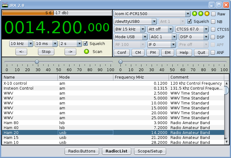
Figure 1: JRX frequency-list display
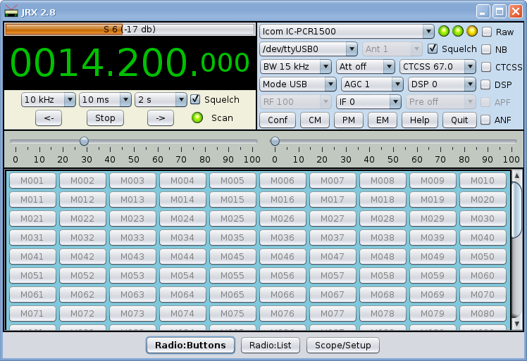
Figure 2: JRX memory-button display
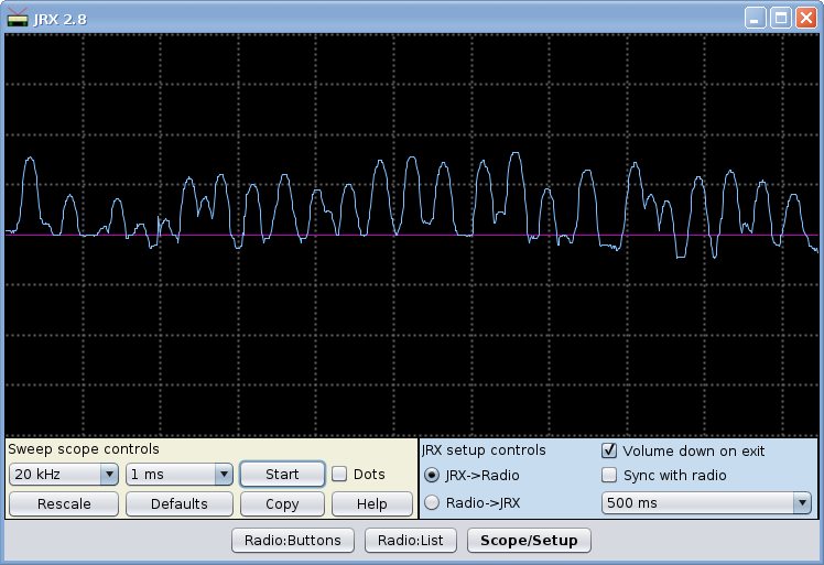
Figure 3: JRX spectrum scope display
JRX is a virtual radio receiver written in Java. It can interface with about 200 radios, thanks to an amazing library called Hamlib, an ambitious project to create a uniform protocol for talking to ham radio transceivers and receivers.
Because JRX is written in Java, it will run on virtually any platform. JRX runs better, faster and more efficiently, on Linux than on Windows, but that's true for most everything.
JRX uses a number of advanced methods to make itself easy to use. To change frequencies, you point the mouse cursor at the digit you want to change and spin the mouse wheel. To recall a saved frequency from memory, you press a button. To save a frequency to memory, you just press the button a little longer (like a non-virtual car radio).
Readers may wonder what purpose is served by virtualizing a radio with controls — after all, the radio already has knobs and dials. What's the point? Well, JRX has 200 read/write memories that are saved between program runs, it has a programmable scanner and spectrum scope, and apart from these features it is much easier to use than a typical radio. And in the case of a radio that requires a computer to control it, there's no contest — JRX is a good choice.
Regular visitors to arachnoid.com may remember I wrote another virtual radio years ago named IcomControl. It was a project with some limitations — it only ran on Windows, and it only controlled one radio (the discontinued Icom IC-PCR1000). Since then I have wanted to revisit this topic and try to improve the quality of virtual radios. I think JRX does just that.
Here's a block diagram in which JRX plays a part:
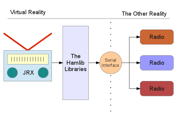
Figure 4: JRX, Hamlib, serial interface, reality
Here are comments about each of these elements:
JRX: Available for download on this page, GPL, open-source (source available), free.
Hamlib Libraries: Also open-source, also free (more information here), and under active development. A remarkable project that is preventing a lot of duplicated effort.
Serial Interface: Most modern computers use a USB adaptor for a serial interface because most computer manufacturers regard an old-style serial port as a throwback in modern times, as well as a waste of precious space on a laptop (and this view has some merit). Hamlib under Linux has no problem working with USB serial adaptors, but Windows is another story.
To make a list of serial interface adaptors with which JRX should work, Google using a search string of "CI-V USB".
Radios: The list of radios that Hamlib supports is astounding (about 200 — here's the list as of 10/18/2012). As to my fanciful diagram showing one serial output feeding multiple radios, this is actually feasible using the Icom CI-V interface (or one of the perfectly good knockoffs), which multiplexes a single serial port to multiple radios (and which Hamlib fully supports). I have a number of Icom radios, and I use the CI-V system with JRX (and Hamlib) to switch radios, so Figure 4 reflects reality.
Before describing JRX in detail, let's deal with installation issues. Listed by platform:
All Platforms:
- Install the most recent Java runtime engine, available here. This is necessary to run JRX, which is a Java program. If you already have Java installed but JRX won't run, chances are you need to upgrade Java to the most recent version. And upgrading Java is a good idea on general principles.
Linux:
- Install the Hamlib libraries — the easiest way is to use a package manager:
- Yum:
yum -y install hamlib- Apt:
apt-get install hamlib- But one can also compile from source if a platform doesn't have Hamlib in prepackaged form.
- To run JRX, move to the directory containing this JAR file, and type:
The above can be easily made part of a shell script.
java -jar JRX.jarWindows:
- Download the JRX Windows installation package and run it (the required Hamlib library is included in the package). The installer will create an icon to run JRX.
- To run JRX, click the desktop icon.
All Platforms:
- Connect a radio that's on this list to your computer by way of a CI-V / USB adaptor or another suitable interface method, power it up, and run JRX.
- On the JRX display, locate the radio selector drop-down list (initially it will show "-- Select a radio --") and choose your radio model.
- On the JRX display, locate the communication interfaces drop-down list (initially it will show "-- Select an interface --") and choose the appropriate interface.
- After the above steps have been taken, and assuming everything is working, the radio should show signs of being controlled, for example by changing its frequency to agree with JRX.
- To be sure things are working, try changing frequencies with JRX — point your mouse cursor at the frequency display (Figure 1, large green digits) and spin your mouse wheel. If you don't have a mouse wheel, click the top or bottom of the digit you want to change. The real-world radio's frequency should change in step.
JRX Source:
- In keeping with the spirit of open source, I offer the full JRX Java source as a TAR archive. Users are free to make their own versions of JRX to suit particular needs, but if you're thinking about distributing a derived version, be sure to read the GPL. The JRX source is organized as a Netbeans project.
Not only is JRX not like a typical hardware radio, it's not like a typical software radio either — it's better :).
JRX uses the latest human-interface technologies and ideas to be easy to use and intuitive. Most control actions involve intuitive pointing and clicking, spinning the mouse wheel, plus some actions that mimic real-world skills the user may have acquired, like changing the memory-button settings on a car radio.
Choosing a Frequency
At first glance it may not be obvious how to change frequencies — there's no frequency entry window, and there are some big green frequency digits that appear to be only for display. But take a closer look — point your mouse cursor at one of the big green digits, then spin the mouse wheel. This feature works on a digit-by-digit basis, which means with practice you can move to a new a frequency very quickly.
If your pointing device doesn't have a wheel, click the top or bottom of the digits to change their value. Almost as fast as a wheel.
Memory Scanning
The other way to change frequencies, perhaps while hunting for a signal, is to scan. Below the green digits are some drop-down lists, arrow buttons and a "Stop" button — this is the primary scanner. To use it, choose a scan step and speed (these controls also accept mouse wheel control), save start and end frequencies in memory buttons, click one of the buttons defining the start and end frequenies, then click one of the scan arrow buttons to start. The scan commences at the lower of the two frequency you saved, and increments using the frequency step size you've chosen. Here are some examples:
Let's say it's after dark and you want to scan the AM broadcast band for distant stations:
- At the upper right, choose the AM mode and set the bandwidth to "Auto".
- With the green frequency display digits and the methods described above, set a frequency of 540 kHz.
- Because you're new to JRX and because there are so many digits in the display, 540 kHz is:
0000.540.000- Just remember that the right-hand decimal point partitions Kilohertz and hundreds of Hertz, and the left-hand decimal point partitions Megahertz and hundreds of Kilohertz. The very rightmost, small, digit has units of Hertz.
- Choose a scan step of 10 kHz (the U.S. AM broadcast station interval) and a scan speed that's slow enough to allow you to listen for a few seconds to each scanned station.
- Save the 540 KHz frequency in a memory button — just choose a memory button and use your mouse cursor to press it for more than one second (which saves the frequency).
- Now use the above tuning method to move to 1600 KHz.
- Save this frequency in a memory button adjacent to the first.
- Now click the right arrow to start scanning.
- If the squelch is set too low, the scan won't start — raise the squelch setting to allow scanning to commence.
- If you hear something noteworthy, click "Stop".
- To resume your scan, press the right arrow again.
- To reverse direction, press the left arrow.
Let's say you're several decades younger than the person who ran the above example and you want to scan the FM band instead:
- At the upper right, choose the WFM mode and set the bandwidth to "Auto".
- With the green frequency display digits and the methods described above, set a frequency of 87.9 MHz.
- Because you're new to JRX and because there are so many digits in the display, 87.9 MHz is:
0087.900.000- Choose a scan step of 200.0 kHz (the U.S. FM broadcast station interval) and a scan speed that's slow enough to allow you to listen for a few seconds to each scanned station.
- Much as above, save the frequencies of 87.9 MHz and 108.3 MHz in adjacent memory buttons, then click the right arrow to start scanning.
Program Scanning
In the above scanning example, we defined two memory buttons for a simple scan between two frequencies (a "memory scan"). In this example we define more than two adjacent buttons, which creates the conditions for a "Program scan", or a scan to specific frequencies defined in a set of more than two memory buttons.
In this example, select a set of frequencies you're interested in scanning and program them into a row of adjacent memory buttons. Then, before brginning the scan, click either the first or last button in the defined set (the boundaries of the set are undefined memory buttons). Then click one of the scan arrow buttons as above.
To skip one of the defined memories without erasing it, right-click that button and its text will turn blue, indicating that it will be skipped during the program scan.
All your memorized buttons are saved between program runs, along with many other JRX settings.
Frequency Selection and scanning from a Table
Recent JRX versions have a frequency table the user can click to change frequencies, as well as scan in much the same way as with memory buttons. To access the table, select the "Radio:List" tab on the main display. Frequencies may be selected by pointing and clicking the chosen frequency, or by using the up and down arrow keys once an initial frequency has been selected.
To use the frequency table for scanning, select two or more frequencies, then press the "->" or "<-" buttons on the scan panel. The frequencies you select don't need to be adjacent to one another in the table. To choose more than one frequency, press the control key down while selecting frequencies. To select a block of frequencies, select a start frequency, then hold the shift key down as you select the end frequency.
As with the memory-button scanning method described above, if you select just two frequencies, the scan increments between the chosen frequencies. If you select more than two frequencies, the scan visits the frequencies you choose.
This table is user-customizable — by default it contains frequencies I found intersting or useful, but users aren't required to share my tastes :). The source file for the table is located on your system at (user home directory)./JRX/frequencies/default.tsv.
The file is organized as a tab-separated-value (TSV) plain-text data table. This file's contents can be copied into a spreadsheet program for convenient editing, then the results can either be saved as a tab-separated-value file or the spreadsheet's contents can be copied into a plain-text document — when commanded to make a clipboard copy, most spreadsheets will write a tab-separated-value version of the spreadsheet data onto the system clipboard.
When editing the table, remember that frequencies are expressed in megahertz, and don't try to rearrange the record fields or delete any of them — this will cause JRX to become confused (the names don't need to remain the same, but the field positions do). Also, if you decide you don't like your custom table, just delete the edited table and run JRX again — JRX will recreate the default table.
If the user prefers, he can add any number of additional TSV formatted files to the (user home directory)/.JRX/frequencies directory, each with the same naming convention as the default file, i.e. "yourname.tsv". At program start, JRX will read all the files and assemble them into a master frequency list. This arrangement allows a long frequency list to be broken up into logical groupings.
Receiver Configuration
At the upper right of the receiver display is a panel with many configuration controls, not all of which will work in each radio (controls that don't work with the current radio are grayed out). Most of these controls can be changed using the mouse wheel rather than selecting from a drop-down list. (Controls that have the mouse-wheel feature contain a wheel symbol (❃) in their flyout description.)
There is one important note about these controls — some combinations of mode and bandwidth won't work. For example, the wideband FM (WFM) mode probably won't function with a selected bandwidth of 500 Hz. So remember, if the radio refuses to accept your mode entry, try it again using a bandwidth of "Auto".
JRX Configuration
On the "Scope/Setup" tab are some setup and configuration controls:
- JRX -> Radio: At startup, this selection programs the radio with JRX's settings.
- Radio -> JRX: At startup, this selection programs JRX with the radio's setting, just the opposite of the above.
- Volume down on exit: This option automatically zeros the radio's volume setting when the user exits JRX.
- Sync with radio: This experimental feature tries to dynamically synchronize JRX's controls with those on the radio in real-time, even as those control settings are changed on the radio. This feature won't always work as expected, especially with radios having slow communications channels, or if the update speed is set too high (see below).
- Control/Event upate timer: This sets the timing interval for the JRX "heartbeat" timer that governs how often JRX updates its controls. Infrequent is better and more stable, but there may be circumstances where a rate faster than about 500ms is desirable, assuming it's possible. The longest time setting is "off", which, according to persistent rumor, is a very long time. In the "off" position, the s-meter won't be updated, although many other things still work. For most JRX activites, especially the control synchronization feature described above, a normal timer duration is required.
Command-line Arguments
JRX can be configured to some degree from the command line. If the user starts JRX with a command-line argument of "-h", this will appear:
These command-line arguments allow the user to control JRX at a more basic level than by way of its user interface, as well as solve certain kinds of problems:Usage: -r com port (COM1, /dev/ttyUSB0, etc.) -m radio code number (as with rigctl) -M "radio name" (IC-756, etc., quoted) -d (debug) 0,1,2 -t (run event timer) 0 = no, 1 = yes -i initialize radio settings to defaults, no arg (doesn't lose memory or other settings) -h this help and exit
- -r: This works just like the same argument in "rigctl" and "rigctld" — it allows the user to specify a communications port. This option allows entry of any communication port name and path, not just a typical one like COM1 (Windows) or /dev/ttyUSB0 (Linux). If a port path is entered, the interface selector dialog is grayed out and the user's specification is used instead.
- -m: This accepts the same rig code numbers that "rigctl" does, and, as above, grays out the selector dialog.
- -M: Unlike "rigctl", users can type in the name of their radio and it will be accepted, as long as it's spelled exactly the same as it appears in the radio list provided by "rigctl -l". If the radio name includes spaces it's necessary to enclose it in quotes to have it be accepted.
- -d: a debugging feature, useful for development work, that I am leaving in because I expect there will be more changes in the future, and possibly even a few bug reports. :)
- -t: This stops the event timer, regardless of the setting that's been made for it. This is useful to deal with certain development and tracing issues.
- -i: This feature resets radio-related settings (i.e. radio model and com port) and most other JRX settings to their defaults, but without erasing memory buttons. This can help recover from certain problems that come up when changing from one radio to another.
Squelch Schemes
Many radios don't provide a squelch state (DCD) signal, which makes designing a programmed scanner rather difficult. Normally, a programmed scanner stops when it detects a signal, but without squelch-state information from the radio, a different scheme must be used to decide when to stop scanning. JRX deals with this problem this way:
- If the radio provides a squelch (DCD) signal:
- JRX uses its squelch control to adjust the radio's squelch level and provide the desired threshold level.
- the JRX programmed scanner samples the radio's squelch level to decide when to stop scanning.
- If the radio doesn't provide a squelch (DCD) signal:
- JRX has a scheme that, when enabled (select "Squelch"), creates a local squelch signal based on the difference between the radio's signal strength and the local squelch control.
- If the local squelch level isn't exceeded, JRX mutes the receiver's audio and allows the programmed scanner to scan.
- If the local squelch level is exceeded, JRX unmutes the radio's audio and stops the scan.
- In most cases, the difference between having a real radio-derived squelch signal, and using the JRX local squelch scheme, won't be significant.
- There is a special case in which a radio doesn't provide a squelch signal but has a tone squelch (CTCSS) feature:
- In this case, to enable the radio's tone squelch feature, the user must disable the JRX local squelch scheme by deselecting the "Squelch" checkbox.
- Deselecting the "Squelch" checkbox disables the JRX scanner, because in that case it would have no squelch signal to control the scan.
- This means that, for a radio without a squelch signal, JRX scanning can't use the radio's CTCSS tone squelch feature as the basis for stopping a scan, only ordinary squelch based on signal strength.
Memory reading and writing
As you move through examples like those above, it may occur to you that it would save time to store your frequency and mode choices for later recall. JRX has 200 available memories, arranged as a scrollable list of buttons at the bottom of the receiver display.
To save all the current settings (not just frequency), press a memory button and hold it down for one second. This is meant to remind users of a car radio, which uses the same scheme to distinguish between reading and writing memory.
To recall a stored setting, press its button briefly. Remember that JRX memory buttons store all the receiver settings — frequency, mode (AM/FM/etc.), bandwidth, volume and several other settings. Remember also that your saved settings are retained for later JRX sessions.To erase a memory, click its button with the right mouse button and hold for more than one second (a short right-click skips that button during program scanning). You will be asked to confirm the erase choice.
JRX has two tabs — the one marked "Receiver" has the receiver display described above, and the one marked "Scope" has a scanning scope display.
The scanning scope is useful for locating signals and for analyzing receiver performance with different bandwidth and other settings. To use the scanning scope:
- At the "Receiver" tab, choose a starting frequency, a mode and other properties for the scan.
- Save your choices in a memory location — let's say for this example that you saved your choices in memory location "M005" (it can be any location).
- Choose an ending frequency, the point at which you want the scan to end.
- Save this frequency at a memory location one higher than the frequency chosen above — in this example, that would be memory "M006".
- Quick review:
Memory location "M005" contains the starting frequency and mode for the scan.
Memory location "M006" contains a frequency that is higher than the starting frequency, and is the desired ending point for the scan.
(Any pair of memory buttons can be used for setting spectrum limits.)- Now click either of the defined memory buttons.
When setting up for a scan, remember that the most recently clicked memory location must be one of the pair of locations that contain the starting and ending frequencies (in this example, "M005" and "M006"). Always click one the defined pair before moving to the scope tab.- Move to the "Scope/Setup" tab and choose a frequency step size for your scan.
Small frequency steps give more detail, but require more time to scan.- Choose a scan speed. This setting determines the time interval between radio frequency changes.
This setting requires some experimentation, because radios differ in how fast they can respond to a frequency change and signal strength poll. The best receivers in my experience will deliver samples on a 12 millisecond interval (that's more than 80 samples per second). The worst may require 250 or more milliseconds. The symptom of setting too fast an interval is that the radio produces samples at its own internal rate, disregarding the interval chosen by the user.- Press "Start" and the scan will begin.
- If the scan isn't going as expected, just press the Start/Stop button again.
- As the scan progresses, if you want to expand the vertical scale, press "Rescale".
If you would like to save the data from the scan for further analysis, press "Copy".This action places the scan dataset onto the system clipboard in a form suitable for saving in a database or pasting into a spreadsheet (as CSV or "comma-separated values").- Figure 3 on this page shows what a completed scan looks like, but there are a number of subtle considerations to getting a good scan. Here's one example:
A typical AGC system will cause problems for a receiver analysis scan, because most AGC systems react too slowly, even when AGC is set to "fast". I solve this problem by using FM instead of AM or USB/LSB when scanning. For a number of reasons, scanning in FM mode produces very fast responses to changes in signal level.- During and after a scan, to investigate its properties, move the mouse cursor across the scan image. The X and Y coordinates of the point under the mouse cursor will appear as flyout text. This allows you to easily identify the frequency and amplitude of any interesting features.
To answer what may be an obvious reader question at this point, yes, I'm a ham — KE7ZZ. I don't operate much — I'm more interested in designing software that either controls radios or processes their signals (Examples: JNX, JWX, IcomProgrammer, IcomControl). But I've been a ham continuously for over 50 years. Ham radio was particularly useful to me during my around-the-world sail, where I operated much more than usual, possibly because I was sailing solo, surrounded by thousands of miles of empty salt water.
JRX retains all of its settings between uses, including all user-defined memory entries. This data is stored under the user's home directory in a directory named ".JRX". I cannot overemphasize how much of JRX's program state is saved between uses — even the user's adjustments to the application window position and size are retained and then restored on the next invocation.
Because the many radios compatible with Hamlib have different supported features, when JRX runs it polls the radio to see which panel controls to enable. This means there will almost always be some disabled panel controls — this is normal.
At the end of my around-the-world sail about 25 years ago, after watching any number of radios die in the presence of salt water (or even a suggestion that there might be salt water sometime in the future), I decided there wasn't any point in owning radios other than Icoms. Since then I have accumulated quite a few Icom radios (IC-PCR1000, IC-R8500, IC-746, IC-756Pro, IC-706) and I have tested JRX with all of them.
This has the advantage that I've tested JRX with a lot of different radios, including a problem-child radio (the PCR1000) that tends to react too slowly. The bad news is that, if there are any pecularities in Yaesu or Kenwood radios that aren't present in Icom radios, I can't take them into account. I would like to hear from those who have these other radios (post to my message board) with operating notes and bug reports. Even though I'm interested to hear how well or poorly JRX does with these other brands, I probably won't be able to fix non-Icom bugs because I don't own the radio in question.
While designing JRX, interested mostly in receiving and concerned that the project was getting too complicated, I decided not to try to include transmitter functions. Because JRX is open-source, others are welcome to expand the project to suit their own tastes.
There are some gaps in the Hamlib protocol, gaps where a feature appears to be supported, but isn't, or not supported in a coherent way. One of these is AGC mode control. On most radios, Hamlib seems to have the ability to control the AGC mode (fast, medium, slow), and careful experimentation seems to confirm that Hamlib does change the AGC mode, but in a random mapping of control numbers to AGC modes from radio to radio.
When I started programing the AGC feature, I searched the literature (The Hamlib help pages, the source-code listings and other sources), and I found this in the Linux man page for rigctl:
AGC (0:OFF, 1:SUPERFAST, 2:FAST, 3:SLOW, 4:USER, 5:MEDIUM, 6:AUTO)But after extensive testing, this mapping of commands to numbers didn't work out — even though all my radios are Icoms, each has different numbers it responds to. I finally gave up and created a really dumb list of AGC numbers (0 through 9) that, once chosen, will be retained by JRX and that become part of each memory record. It would obvously be much nicer if Hamlib actually had a command-to-number mapping as it does for so many other functions, with specifics for each radio. If this change was made, I would quickly reprogram JRX to take this into account, and avoid the present list of uninstructive values: "AGC 0, AGC 1, AGC 2...".
While developing JRX, I did most of my testing on the Icom IC-PCR1000, a discontinued radio that richly deserved to be discontinued. This choice turned out to be wise, because the PCR1000 has some peculiarities that forced me to program carefully to accommodate it. As it turns out, Icom has replaced this radio with a new model that has a USB interface and I thought might be better (IC-PCR1500). I picked up the new model and, after adding a delay-parameter dialog to JRX, I was able to get the new Icom radio to scan as fast as its literature claims — in fact, faster. The specifications for the PCR1500 claim it can scan at a rate of 60 samples per second. At first I didn't get anywhere near this result, but after careful detective work I discovered that the Hamlib default communications-delay settings for this model were quite wrong, and were keeping the radio from performing as it should.
After adding a communications parameter dialog to JRX and setting all the delays to zero, this radio started delivering samples at a rate of one every 11 or 12 milliseconds (that's more than 80 samples per second) — which makes it the fastest radio I own (a rather large set that includes an IC746, IC756Pro, ICR8500 and an IC706MkII). To be specific, a scanning "sample" consists of a change of frequency command followed by a poll of the resulting signal strength, which requires two transmissions and replies.
Editorial comment: The older PCR1000 radio's reputation for slow communications is richly deserved, but the new radio represent a huge improvement in performance — once the Hamlib parameters are tuned. For the record, this is how one invokes the rigctld daemon for maximum performance from a radio like the PCR1500:
rigctld -m 403 -r (com port) --set-conf=write_delay=0 --set-conf=post_write_delay=0The above settings differ greatly from the delays for the PCR1500 programmed into Hamlib, and the defaults only allowed one sample every 230 milliseconds, which (a) is dead slow, and (b) would mislead one into thinking there was no difference between the new and old radios — which I confess I thought for a few days until I was able to identify the cause of the delays and fix them, the topic of the next section.
I include this detailed description so others who must analyze USB serial transactions will know how easy it is — at least, under Linux.
First, using the Hamlib utilities rigctl and rigctld from the command line is a pain because they don't support history — if you type something, however complex, it's gone forever. If you need that same command, you type it in again. To get around this limitation I wrote a small shell utility — rigctld_with_history.sh. It saves me a huge amount of time while debugging.
During my analysis of the above communication-speed issue, I realized the problem might not be intrinsic to the radio — Icom claims it can gather 60 samples per second, also the Icom-provided radio software runs very fast, unfortunately that software is only available for ... umm ... that other operating system. So, confronted by these facts, I asked myself many questions — was I creating my TCP/IP socket incorrectly or doing anything else in my progam that resulted in slow communications?
It eventually occurred to me that to sort things out I needed to look at the actual bytes flowing to and from the USB-connected device, with no intermediaries. As it turns out, modern Linux kernels have such a method available — a driver called usbmon that monitors USB transactions. To see whether your Linux installation has this driver, type this into a shell session:
$ ls /sys/kernel/debug/usb/usbmon/The '$' at the left is the user-level session prompt — you don't type it. And in this and later examples, the user's typing looks like this, and the system's replies look like this.
If the above command produces an error message "No such file or directory", install usbmon (as root) before going on (this example is for a recent (late 2012) Fedora Linux distribution):
# yum install usbmonSide note — once the usbmon kernel driver is installed, on Linux systems Wireshark can monitor USB traffic by specifying an interface of "usbmon(bus number)", example "usbmon1". In this example, because I wanted to copy the raw output for use in this page, I used the command-line usbmon utility, but this isn't the only way to monitor USB transactions.
On my system, because usbmon (both the kernel driver and the command-line interface) is installed, on my system the above command yields this:$ ls /sys/kernel/debug/usb/usbmon/ 0s 0u 1s 1t 1u 2s 2t 2uThe entities in the reply are USB bus numbers (0,1,2), plus identifiers for the varieties of output that usbmon creates (s,t,u).
To acquire transaction data for a specific USB device, we first need to find out to which bus the device is attached. On my system, I type this command and get this result:I include this level of detail so the reader will appreciate how complicated it can be to identify a particular device in a modern desktop environment. For the above list I have the target device plugged in, but I don't really know which of the above-listed devices is the desired target. So I proceed this way:$ lsusb Bus 001 Device 002: ID 05e3:0608 Genesys Logic, Inc. USB-2.0 4-Port HUB Bus 001 Device 003: ID 05e3:0608 Genesys Logic, Inc. USB-2.0 4-Port HUB Bus 001 Device 004: ID 05e3:0608 Genesys Logic, Inc. USB-2.0 4-Port HUB Bus 002 Device 002: ID 03f0:0217 Hewlett-Packard LaserJet 2200 Bus 002 Device 003: ID 413c:1002 Dell Computer Corp. Keyboard Hub Bus 001 Device 001: ID 1d6b:0002 Linux Foundation 2.0 root hub Bus 002 Device 001: ID 1d6b:0001 Linux Foundation 1.1 root hub Bus 001 Device 007: ID 05e3:0702 Genesys Logic, Inc. USB 2.0 IDE Adapter [GL811E] Bus 001 Device 008: ID 05e3:0702 Genesys Logic, Inc. USB 2.0 IDE Adapter [GL811E] Bus 001 Device 009: ID 05e3:0702 Genesys Logic, Inc. USB 2.0 IDE Adapter [GL811E] Bus 001 Device 010: ID 0a12:0001 Cambridge Silicon Radio, Ltd Bluetooth Dongle (HCI mode) Bus 001 Device 011: ID 046d:0809 Logitech, Inc. Webcam Pro 9000 Bus 001 Device 024: ID 0424:2502 Standard Microsystems Corp. Bus 002 Device 004: ID 413c:2002 Dell Computer Corp. SK-8125 Keyboard Bus 002 Device 005: ID 045e:0040 Microsoft Corp. Wheel Mouse Optical Bus 001 Device 025: ID 08bb:2901 Texas Instruments Japan PCM2901 Audio Codec Bus 001 Device 026: ID 10c4:ea60 Cygnal Integrated Products, Inc. CP210x Composite Device
- With the device plugged into the USB bus, I enter this command:
$ lsusb > with.log- Now I disconnect the target device and type this:
$ lsusb > without.log- Now, to locate the entries associated with the USB peripheral, I type this:
$ diff with.log without.log | grep '<'

< Bus 001 Device 024: ID 0424:2502 Standard Microsystems Corp.
< Bus 001 Device 025: ID 08bb:2901 Texas Instruments Japan PCM2901 Audio Codec
< Bus 001 Device 026: ID 10c4:ea60 Cygnal Integrated Products, Inc. CP210x Composite Device
The device in this example is an Icom IC-PCR1500, a relatively new headless radio (a radio that requires a computer interface) that's discussed in the previous section. From the above result I realize this radio has three USB devices mediated through one USB connection, and I decide the USB device I want to monitor is 001:026. So I try to start monitoring like this:
$ usbmon -i 1 | grep :026:

usbmon: Must run as root
Okay, that was foreseeable — sampling usbmon's output requires root privileges. So I open a separate root shell session and say:
# usbmon -i 1 | grep :026:Note the change in the shell prompt: '#', meaning root access. The above command is issued in a root-access shell session, while the user-level commands below are issued in a separate, user-level session. With the "grep" filter I limit the outputs from USB bus 1 to the specific device I'm interested in monitoring (device 026).
Now I need to start a source for USB bus traffic. First, I make sure I've installed the Hamlib libraries:
# yum install hamlibNow I start the Hamlib TCP/IP daemon like this (and remember this can be done using my rigctld with history utility):
$ rigctld -m 403 -r /dev/ttyUSB0 &The above specifies the IC-PCR1500 code that Hamlib knows (403), and specifies the USB port it's attached to (/dev/ttyUSB0).
Launching the Hamlib daemon creates a huge amount of traffic on the USB bus as the peripheral is initialized, which I won't summarize. Now to issue a radio command to the Hamlib daemon:
$ time echo 'L AF .1' | nc localhost 4532

RPRT 0

real    0m0.077s
user    0m0.002s
sys     0m0.000s
That required 77 milliseconds. Over at the usbmon logging window, initialized above, for this command we see:
c4f54300 0.140954 S Bo:1:026:3 - 1 = 4a
c4f54300 0.141936 C Bo:1:026:3 0 1 >
c4f54300 0.154917 S Bo:1:026:3 - 1 = 34
c4f54300 0.155938 C Bo:1:026:3 0 1 >
c4f54300 0.167024 S Bo:1:026:3 - 1 = 30
c4f54300 0.167935 C Bo:1:026:3 0 1 >
c4f54300 0.179106 S Bo:1:026:3 - 1 = 31
c4f54300 0.179934 C Bo:1:026:3 0 1 >
c4f54300 0.191184 S Bo:1:026:3 - 1 = 39
c4f54300 0.191936 C Bo:1:026:3 0 1 >
c4f54300 0.203260 S Bo:1:026:3 - 1 = 0a
c4f54300 0.203937 C Bo:1:026:3 0 1 >
c4f540c0 0.206432 C Bi:1:026:3 0 6 = 47303030 0d0a
c4f540c0 0.206437 S Bi:1:026:3 - 256 <
For these usbmon options, the second column is elapsed time in seconds, important for what's coming up. The entire transaction required (0.206437 - 0.140954) 0.065483 seconds or just over 65 milliseconds. But look closely at the time data — the first 12 rows are the data that Hamlib transmitted to the radio — esentially, in ASCII, "J4019" or the PCR1500 code for a volume level of 10% of the maximum.
Let's take a closer look at this transaction — in time the rows break down this way:
Elapsed sec Traffic Delta-t ms 0.1410 4a (J) 0.1419 > 1.0 0.1549 34 (4) 13.0 0.1559 > 1.0 0.1670 30 (0) 11.1 0.1679 > 0.9 0.1791 31 (1) 11.2 0.1799 > 0.8 0.1912 39 (9) 11.3 0.1919 > 0.8 0.2033 0a (linefeed) 11.3 0.2039 > 0.7 0.2064 47303030 0d0a (G000) (cr/lf) 2.5 0.2064 < 0.0 So it seems that, in this Hamlib transaction, the characters are transmitted separately and delayed, and the delay is just under 12 milliseconds per character.
In the next example, we change the radio's frequency:
$ time echo 'F 540000' | nc localhost 4532

RPRT 0

real    0m0.234s
user    0m0.000s
sys     0m0.001s
Yipes — 234 milliseconds. The usbmon log for this transaction, too long to include, shows a total elapsed time of 220 milliseconds at the USB bus.
At this point I have eliminated my own code from consideration as a source for the slow communications, and have shown that Hamlib is producing long delays. But then it occurs to me that this might be intentional, by design. I do some more reading about Hamlib and realize there are some little-used command-line options that force specific time delays, and one can even discover what time delays Hamlib applies to each radio type.
In this project's ultimate "ah-HA" moment, by reading I discover that I can get Hamlib to tell me what time delay is being applied to any radio model that Hamlib recognizes. I type this:
# rigctl -m 403 -L

( ... )

write_delay: "Delay in ms between each byte sent out"
        Default: 0, Value: 12
        Range: 0.0..1000.0, step 1.0
post_write_delay: "Delay in ms between each command sent out"
        Default: 0, Value: 2
        Range: 0.0..1000.0, step 1.0
timeout: "Timeout in ms"
        Default: 0, Value: 400
        Range: 0.0..10000.0, step 1.0
So there, under "write_delay", is the source of the 12 millisecond delay per character. Apparently those who designed the driver for this radio thought it required the kinds of time delays its predecessor did, probably because no one actually owned this relatively new radio (while plenty of people have experience with its slow predecessor, the PCR1000).
Now that I realize time delays can be set on the command line, I decide to force no delays by launcing the Hamlib daemon this way:
$ rigctld --set-conf=write_delay=0 --set-conf=post_write_delay=0 -m 403 -r /dev/ttyUSB0 &Having restarted the daemon with new parameters, I issue the same frequency-change command as above:
$ time echo 'F 540000' | nc localhost 4532

RPRT 0

real    0m0.011s
user    0m0.001s
sys     0m0.000s
Wow. Eleven millisconds, just 4.7% of the original time (if I was in advertising I would naturally say, "a 2,120% change!"). And the radio has no problem with this data rate.
By the way, here's the usbmon log for the above transaction — much shorter because Hamlib sends commands as full strings when no delays are required:
c4f54300 0.185623 S Bo:1:026:3 - 19 = 4b303030 30303534 30303030 30353032 30300a
c4f54300 0.186557 C Bo:1:026:3 0 19 >
c4f54e40 0.194180 C Bi:1:026:3 0 6 = 47303030 0d0a
c4f54e40 0.194186 S Bi:1:026:3 - 256 <
A total elapsed time of 8.5 milliseconds. By the way, in ASCII, Hamlib said, "K00000540000050200(lf)" (giving a frequency and mode) and in ASCII the radio replied, "G000(cr/lf)", which most people translate into "GOOD".
And that, boys and girls, is why JRX now has a communications parameter tuning dialog.
- Version 3.2 06-06-2013. Recoded to dim unused leading frequency digits, improves display readability.
- Version 3.1 03-05-2013. Changed to a separate frequency-file directory that can contain any number of separate frequency definition files, all of which are read at program start and assembled into a master list.
- Version 3.0 03-04-2013. Fixed a configuration issue that prevented CTCSS squelch operation on radios without native squelch (DCD) capability.
- Version 2.9 02-28-2013. Fixed a race condition in the squelch and scanning code that sometimes prevented the scanner from stopping at the right frequency.
- Version 2.8 02-27-2013. Redesigned the control layout for more efficient use of space.
- Version 2.7 02-26-2013. Fixed another squelch bug that invalidated the squelch state when the volume setting was changed.
- Version 2.6 02-26-2013. Fixed a squelch bug resulting from recent changes, added multiple-frequency selection and scanning from frequency table.
- Version 2.5 02-26-2013. Changed the synthetic squelch scheme to accomoodate some radio models that aren't well-supported by hamlib.
- Version 2.4 02-25-2013. Fixed a bug in the code that manages the two squelch schemes.
- Version 2.3 02-24-2013. Disabled editing of the frequency table cells, which I didn't intend.
- Version 2.2 02-23-2013. Added a clickable frequency table for quick frequency selection from a user-defined list.
- Version 2.1 02-18-2013. Fixed an error in the slow-communications logic that prevented mouse-wheel tuning with slow radios.
- Version 2.0 01-14-2013. Corrected a bug in the volume control logic.
- Version 1.9 11-20-2012. Fixed a few small bugs, reversed the relationship between mouse wheel motion and volume/squelch slider action after discovering there was an established convention for this relationship.
- Version 1.8 11-16-2012. Revised the squelch and DSP schemes to be a bit easier to use.
- Version 1.7 11-15-2012. Refactored the squelch scheme to allow more functions to work when a true squelch level isn't available from the radio.
- Version 1.6 11-15-2012. Fixed a few small bugs resulting from the recent major overhaul.
- Version 1.5 11-14-2012. Reworked much of the code base to simplify and expand the feature set. Added more configuration options and a mini-command-line interpreter. Coded a way for JRX to synchronize itself with a radio's physical controls.
- Version 1.4 11-07-2012. Refactored much of the control code for more comprehensibility and operating speed.
- Version 1.3 11-05-2012. Major revision — redefined the scanning modes to be more consistent with modern scanning methods, added more radio features (i.e. ANF, APF, DSP level control), added a communications speed dialog (explained above) to circumvent some bad Hamlib time-delay data for some radio models, tested on more radios.
- Version 1.2 10-23-2012. Included a Hamlib distribution in the Windows installation executable so the user doesn't need to separately install it.
- Version 1.1 10-22-2012. Fixed some minor bugs, enabled VideoForLinux features for some radios that can be controlled through that interface on the Linux platform.
- Version 1.0 10-19-2012. Initial Public Release.
| Home | | Ham Radio | | | | Share This Page |