

 Share This Page
| Home | | 3D Printing | | | | Share This Page |
More abstraction, better result
— P. Lutus — Message Page —
Copyright © 2020, P. Lutus
Most recent update:
(double-click any word to see its definition)
Update: See the video version of this article.
This page is part of a series about 3D printing mathematical objects. To acquire a context, readers may want to read the first chapter in this series, Platonic Solids I.
In the earlier activity I printed fully three-dimensional Platonic Solids composed of edges, but successful, aesthetically pleasing 3D printed results were difficult to achieve. After some printing experience I began to think about alternatives to printing a Platonic Solid as one piece.
In the phase of my project described here, I decided to try 3D printing individual faces and assemble them into the Platonic Solids. I realized this approach would have the advantage that the faces would lie flat on the print bed. This would solve the adhesion problem and the parts would look much better than the earlier more vertical parts, which were in some cases printed while suspended in thin air.
Planning
It was easy to imagine individual plastic faces lying on a print bed —
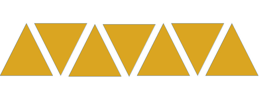
Figure 1: Faces without connectors
— but my goal was to assemble them together into Platonic Solids. For this I needed a way to connect one face to another, something like this:
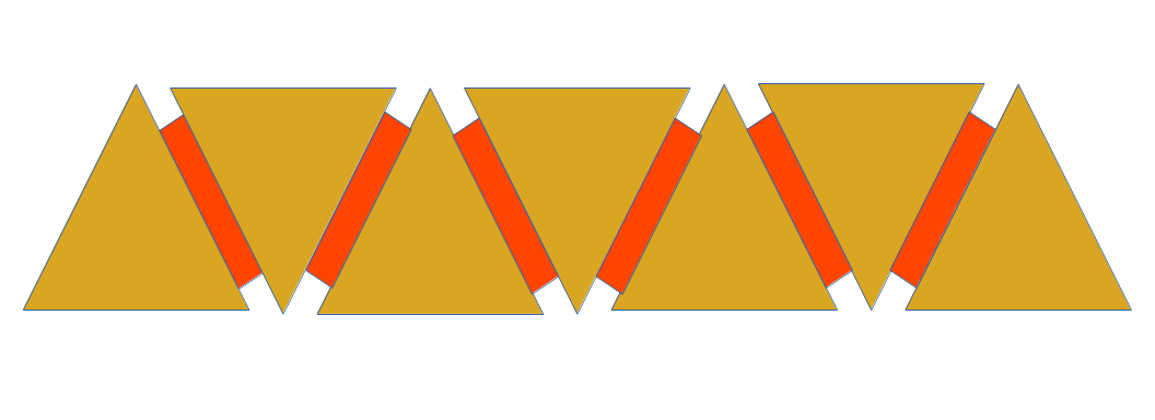
Figure 2: Faces with imagined connectors in red
But what would the attachment be? After some thought I decided my connector had to meet these requirements:
- It should be just one design, not two (plug and socket) — each connector should mate with any other connector.
- It had to act as a hinge as well, because the Platonic Solids have angles between their faces. This meant after connecting, the mated connectors had to freely rotate on their long axis without coming apart.
- The connectors had to fasten firmly, allowing the solid to tolerate forces without coming apart, but the connector also had to separate without breaking. This meant there had to be some flexibility built into the design, maybe flexible lever arms to allow the plastic to bend without breaking.
People familiar with mechanical design will recognize how ambitious this requirement list is. Most connectors are of the plug and socket variety — each connection point requires one of each. And most removable connectors can't also act as hinges because that complicates the design and makes it less reliable.
As I began to think about how to accomplish this, I considered calling the design "unisex," referring to the freedom from distinct gendered parts, but I think that terminology is out of date. So I decided to call it "bilaterally symmetric."
Design
After some thought and experiments, I came up with this design (shown in cross-section):
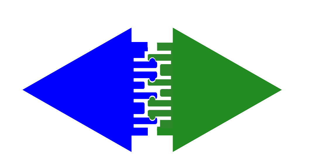
Figure 3: Edge connector/hinge diagram
Notice about the parts shown in Figure 3 that the green triangle is just a copy of the blue one, rotated 180 degrees — they're the same part, but they can be connected to each other.
Here is the FreeCAD dimensional layout for the edge connector (without the fastener spheres):

Figure 4: Edge connector/hinge diagram
In practice, the edge connector/hinge behaves like this:
Figure 5: Edge connector in action
Notice the deep cuts between the connecting fingers in Figures 3 through 5 — these make the fingers flexible enough to firmly connect without breaking under the deforming forces. I must add that I print these parts using ABS filament for its strength — materials like PLA might be too weak and brittle to survive repeated connections and disconnections (I haven't tried PLA yet).
Another advantage of this design is that it's a perfect subject for 3D printing — it lies flat against the 3D print bed, is almost two-dimensional and has no significant overhangs:
Figure 6: Connector design as seen by the Prusa Slicer
So this edge connector design meets all my requirements — it's just one part, it mates with any other connector of the same design, and it doubles as a hinge by rotating freely on its long axis.
Scaling Issues
My first 3D prints of this design were too small in scale and the results were unreliable. Through experiment I arrived at a larger scale where the edge length of the triangles shown in Figures 3 through 5 is 100mm (about 4 inches), and the part thickness is 6mm. This gives the connector probes adequate strength to hold firmly and not wear out too quickly.
It's important to say that for a collection of interchangeable parts, some of which can be re-used to construct different Platonic Solids, the edges must all have the same length. This means the equilateral triangles shown above (which are used to build the octahedron and icosahedron), the 12 pentagons used to build the dodecahedron, and the 20 hexagons and 12 pentagons used to build the Buckyball, all needed to have the same edge length, which I set at 100mm. Unfortunately this made the Buckyball absurdly large, a topic we'll return to below.
First, all the material and files in this project are released under the GPL.
Here are the different forms of this project, as FreeCAD design files and as printer-ready STL files:
Name Used In Number needed FreeCAD design file Printer-ready STL file Image (from Blender)
(click images
for full size)Equilateral Triangle Octahedron, Icosahedron 8,20 Link Link 
Square Cube 6 Link Link 
Pentagon Dodecahedron, Buckyball 12,12 Link Link 
Hexagon Buckyball 20 Link Link 
Table 1: Downloads with details
Notes on Table 1:
- As designed, the equilateral triangle can't be used to build a tetrahedron because the height of the fingers above the body isn't great enough to allow the extreme angle required. A redesign would be required for this specific solid. But see below for a magnetic-attachment version of this solid.
- 12 pentagons are used to build the dodecahedron, and the same number are used in the Buckyball (which also requires 20 hexagons).
- The Buckyball (technically a truncated icosahedron) is the most complex of the solids, and isn't part of the ancient Greek Platonic Solids collection — I added it because it's interesting. It requires 12 pentagons and 20 hexagons.
- Notice that the images aren't in the same scale. Because of the requirement that the edges all have the same length, as the number of sides increases the parts become proportionally larger, and the hexagon measures more than 148mm (5.8 inches) from vertex to vertex. This means the Buckyball ends up being ... huge (see the image below).
Here are pictures of actual assemblies of the elements described above:

Figure 7: Cube (click for full size). Height 95mm (3.74 inches)

Figure 8: Icosahedron (click for full size). Height 173mm (6.8 inches)

Figure 9: Buckyball with cell phone for scale (click for full size). Height 368mm (14.5 inches)
Once I realized how large the assembled parts would be, I tried to think of a simpler design that could be made smaller as well as easier to assemble and break down. I thought about using magnets, arranged like this:
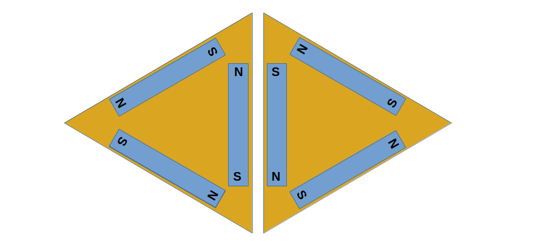
Figure 10: Using magnets as connectors
Notice about Figure 10 that the same logic is used as for the mechanical connector — there should be just one kind of connector, that will naturally fasten to another connector of the same kind.
I ordered some magnets, then designed an equilateral triangle in FreeCAD that would accept the magnets (press-fit) and the result looked like this (as rendered by Blender) before actual printing:

Figure 11: Magnet part design (Blender)
I printed four magnet-ready triangles (enough for a tetrahedron) and pressed some common magnets into place. The finished parts looked like this:

Figure 12: Magnet triangles, 3D printed, with magnets pressed into place
I was unable to find cylindrical magnets with the required dimensions (i.e. 4mm by 40mm), so for each location I stacked four 4mmx10mm magnets as a substitute. Here is how the four magnet-triangles look when assembled as a tetrahedron:

Figure 13: Magnet tetrahedron
But as it turns out, even though I can gently and carefully shape a tetrahedron as shown, the magnets aren't nearly strong enough to support anything larger, so this part of my project will have to wait for better magnets as well as a design that brings the magnets closer together along the edges.
For those who may want to pursue this approach, here are the sources:
This is one of my many projects that try to bring some esoteric mathematics into everyday life. It's been a lot of fun building the Platonic Solids and especially the Buckyball, which came out surprisingly well.
I would like to get better magnets and pursue the magnet-connector variation, because it's much simpler than the mechanical connector. So there's more to be done on this project as I look for better, stronger magnets and try to design the connector to bring the opposing magnetic poles into closer proximity.
And finally, I realize I need to make this a video, because as the years go by fewer and fewer people read printed articles, regardless of their content. So loyal readers, be sure to look for an eventual video version on my YouTube channel.
Update: I made the video. Enjoy!
Thanks for visiting, thanks for reading!
| Home | | 3D Printing | | | | Share This Page |