
 Share This Page
| Home | | 3D Printing | | | Share This Page |
Support and tutorials for this new 3D printer
— P. Lutus — Message Page —
Copyright © 2025, P. Lutus
Most recent update:
(double-click any word to see its definition)
This article introduces and explores the new Prusa Core One printer. It includes a number of methods to increase this printer's accuracy and usefulness. Some printable 3D resources are included, including a Web camera mount to provide a local-network, full color, video frame rate printing monitor, to replace the Prusa Buddy3D camera.
This article describes the Prusa Core One from a user perspective. I have no connection with Prusa, no editorial constraints, and some personal preferences having to do with privacy and independence.
This article assumes you have a working Prusa Core One, either a factory-built machine or a completed kit. This article goes beyond the instructions provided by Prusa and offers some configuration and tuning advice not found elsewhere.
Although this article's focus is the Prusa Core One, many of its methods apply to other Prusa printers.
This article is intended as a resource archive for this YouTube video.
Let's get started!
As delivered, either factory-built or user-assembled, this printer needs certain alignments for best performance, some of which aren't very well documented. This section provides a Z-axis (vertical) alignment method to level the print bed.
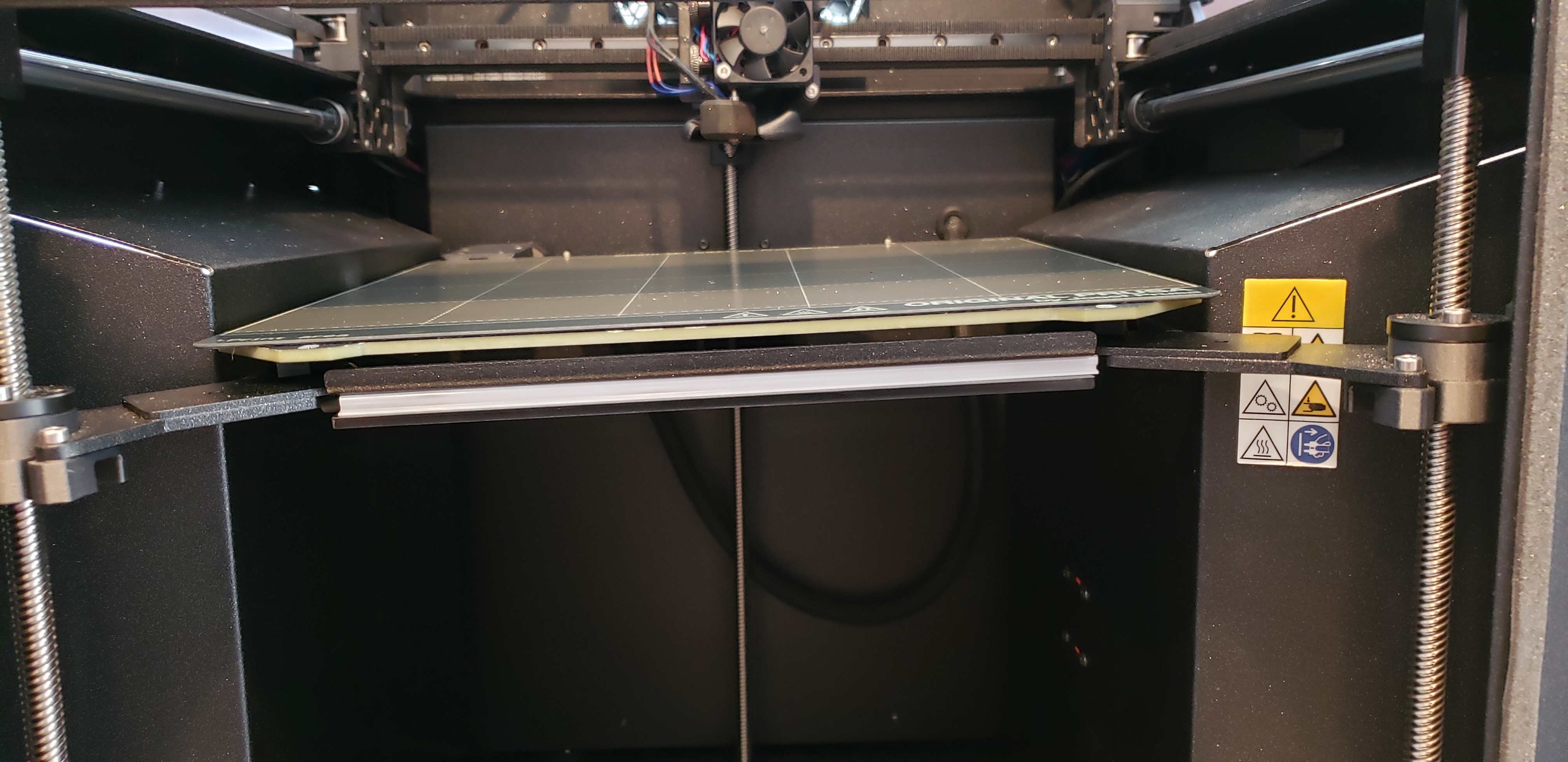
Pathologically Misaligned Print Bed
This image shows a print bed with greatly exaggerated misalignment, just to make a point — if the print bed isn't properly aligned or "leveled", many other things will go wrong. On delivery, many Prusa printers, especially those assembled by the recipient, will have misaligned print beds.
It's important to say the printer will automatically detect and if necessary correct small Z axis misalignments, at the start of each print. This special procedure is meant only for newly assembled / arrived printers, where a Z misalignment may need special attention, to avoid component wear and stress.
Here's the procedure: the Prusa Core One print bed is supported by three threaded shafts, each connected to a stepper motor. The stepper motors operate synchronously, rotating the threaded shafts during printing, so that the bed remains level at all vertical positions — but this is only true if the bed has been properly leveled in advance. In this section we'll make sure the bed is level.
Here are the steps to align the print bed:
- Move the print bed to its lowest position. This is accomplished using the Prusa Core One control menu:
- Start at the main menu control icon
- Move Axis
- Move Z
- Press the control knob to activate motion, so the current position is printed in red
- Rotate the control knob to move the print bed to its lowest position.
- As the print bed arrives at its lowest position, this will likely be accompanied by a grinding or clicking sound — this is harmless but at that point, stop the motion inputs.
- Either activate the "Disable motors" command, or turn off the printer. The latter choice is simpler and safer.
- Manually rotate each of the three threaded shafts counterclockwise (as seen from above) to move the print bed to its lowest position:
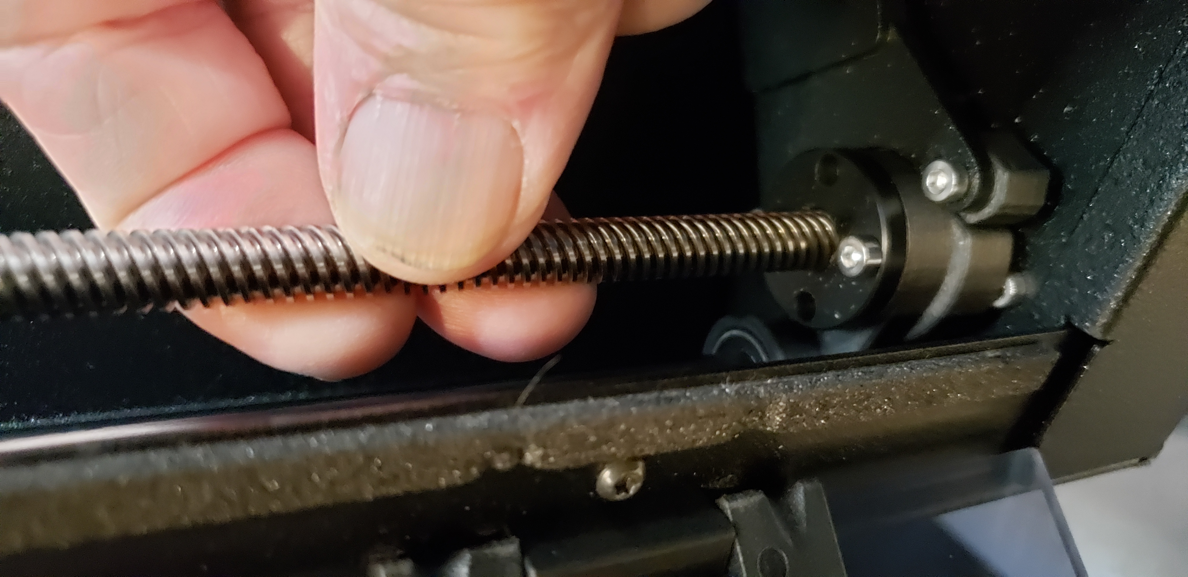
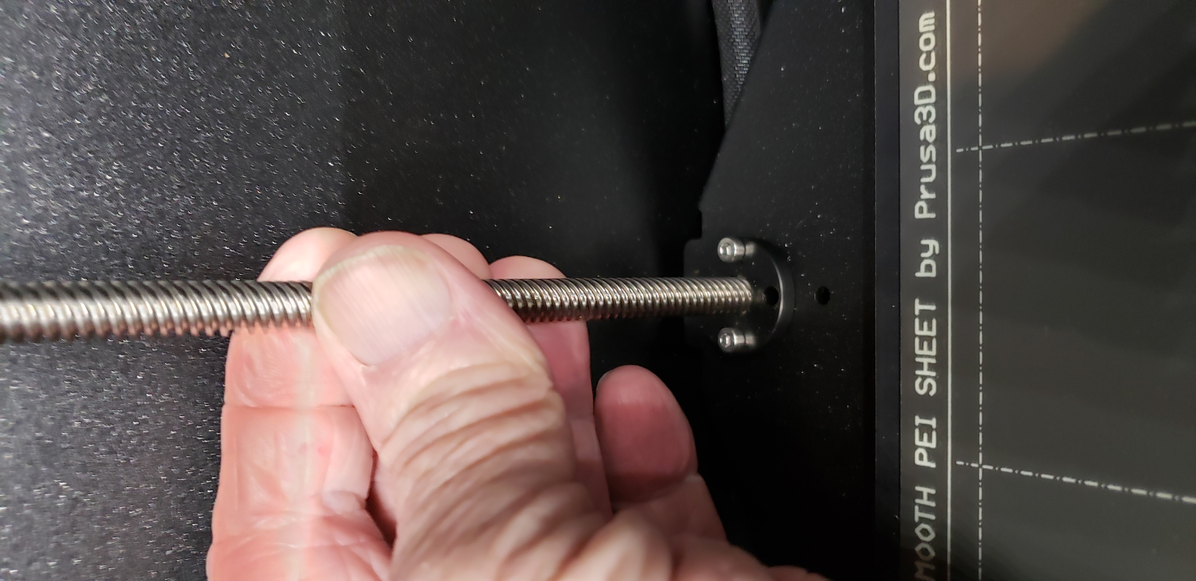
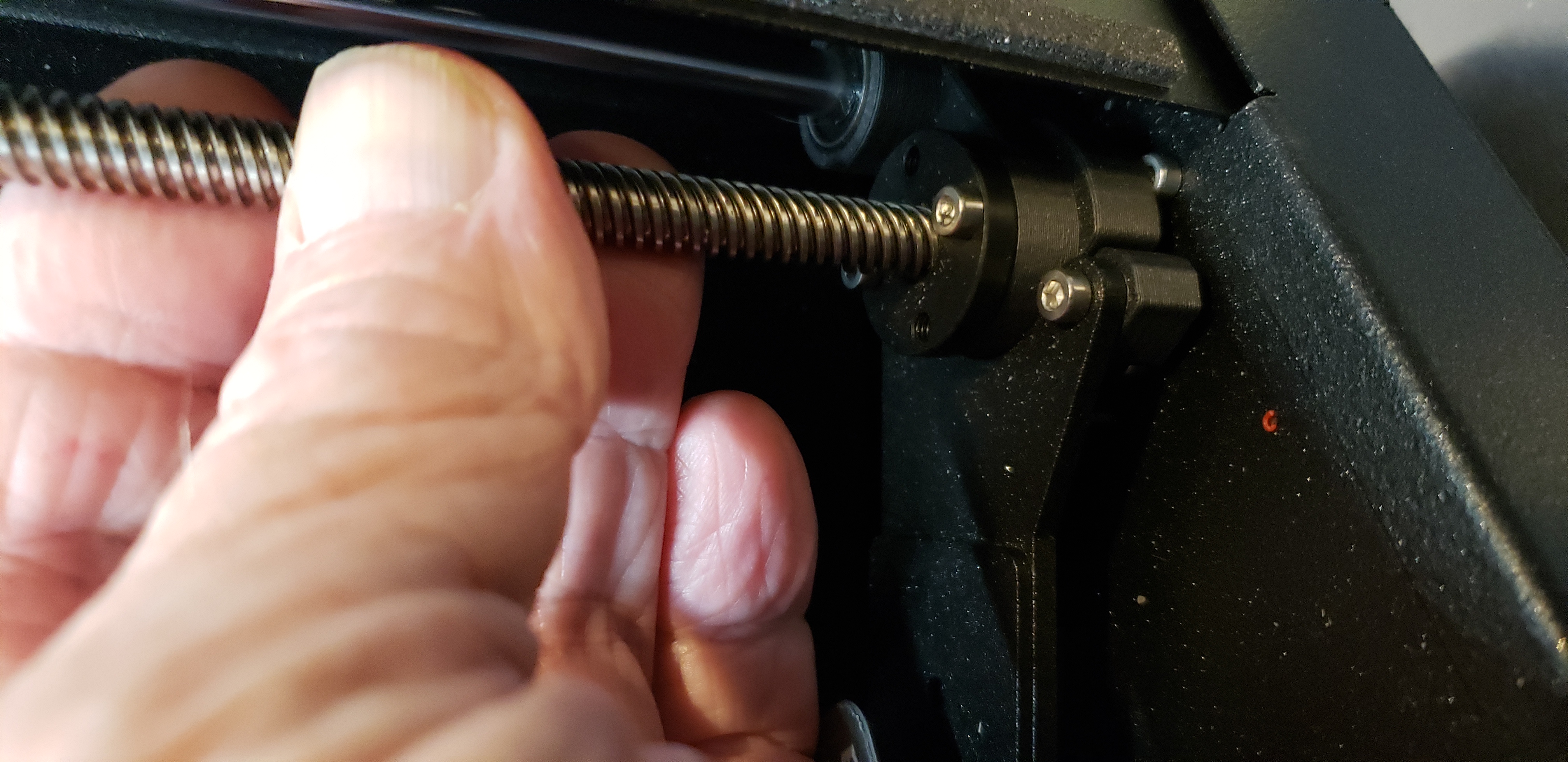
Shaft Rotation to Level Print Bed- This procedure should level the print surface:

Level Print Bed (click for full-size)
The Prusa Core One is designed so that, when the three shafts have been rotated counterclockwise to the degree possible with power off, the print bed will be level. Then, during printing, because the print bed motors are synchronized with each other, the print bed will remain level at all other positions.
After the printer has been given an initial alignment and placed in service, it automatically detects and corrects Z misalignments at the start of each print, so this procedure need only be performed once.
NOTE: This updated alignment method (10.02.2025) replaces an earlier version. This new method is much more reliable than other methods posted online, including those posted by Prusa.
NOTE: If you have never done this sort of thing before, or if you don't feel confident in your ability to carry out this procedure, you can always hire a professional to perform this adjustment for you. Don't forge ahead without an understanding of the process and the possible outcomes.
Unlike Z misalignments, which the printer can automatically correct, XY misalignments require either professional or user intervention. This section explains how to manually correct XY misalignments.
The Prusa Core One uses the so-called "Core XY" scheme, in which the print head's X (left/right) and Y (toward/away) positions are controlled by stationary motors, a long belt, and a system of pulleys. For accurate motions and printing, this scheme requires that the X and Y axes be separated by exactly 90° ("orthogonal"), so that X motions have no effect on the Y dimension and vice versa.
One clue that the X and Y dimensions aren't properly aligned is something called "Print skew":
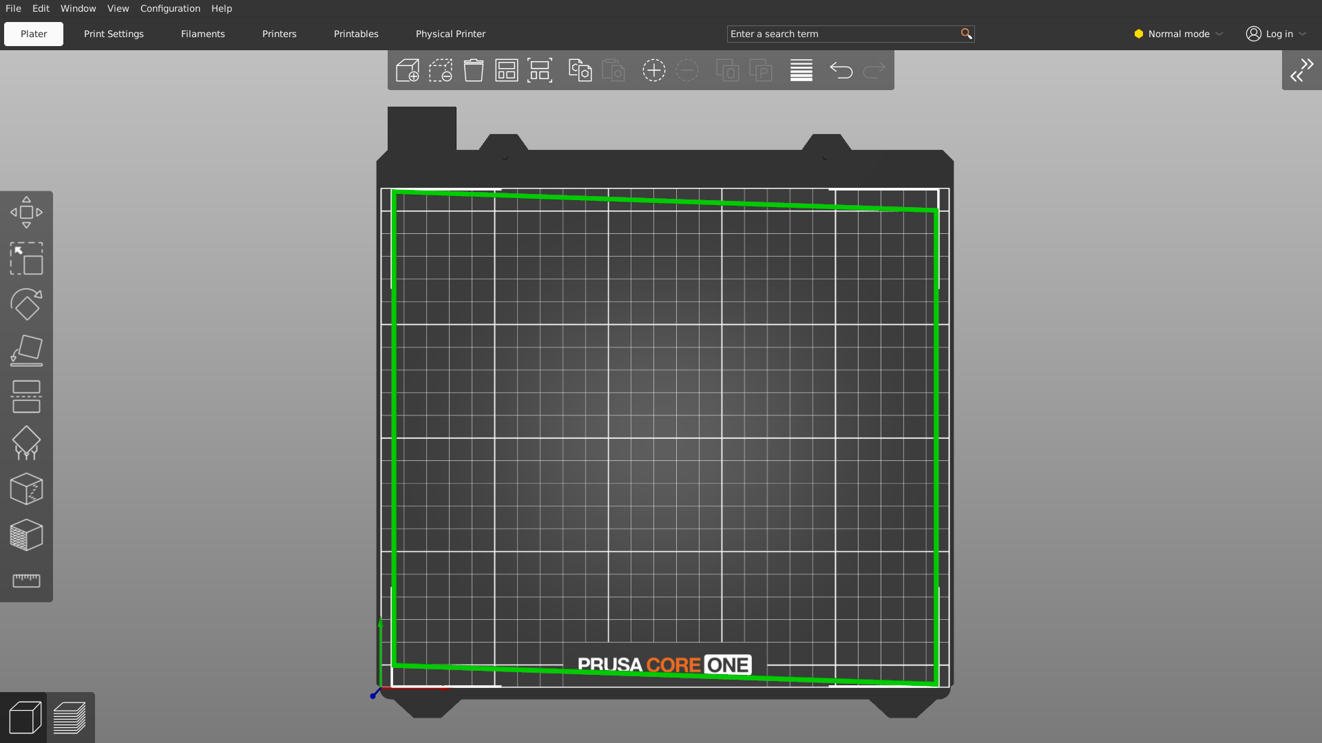
Print Skew (greatly exaggerated)
The effect seen here results from the fact that the printer's X and Y axes aren't separated by exactly 90°. This can have many undesirable effects on 3D printing, as well as cause the Prusa Core One to fail its Y axis motion test:
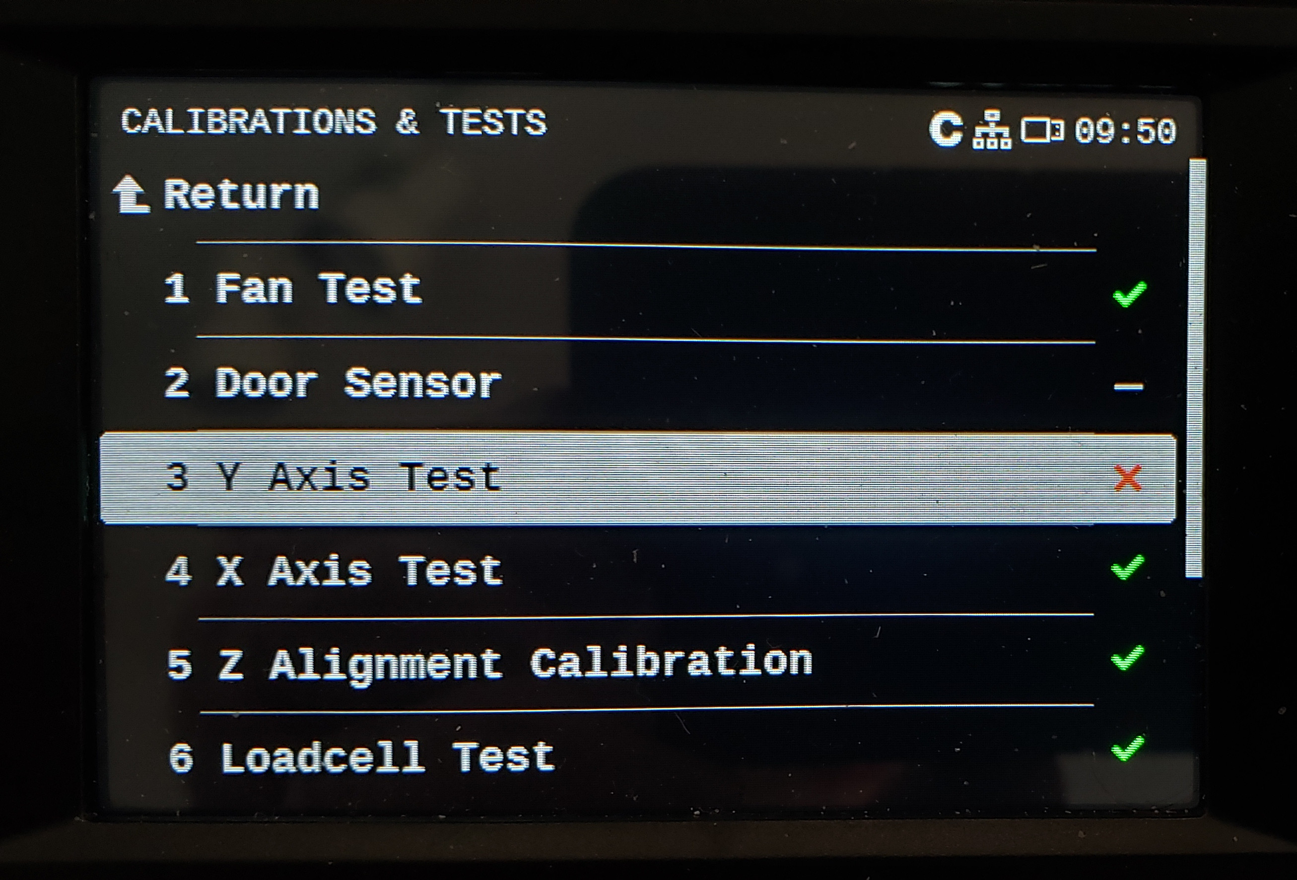
Prusa Core One Y-axis motion test failure
NOTE: If your printer passes its Y axis test and is behaving correctly, then skip this section — there's no need to carry it out and it represents a risk if not performed correctly.
The remedy for X/Y misalignment is to tune the relationship between the X and Y axes so they are "orthogonal," meaning separated by exactly 90°. Unlike the Z axis adjustment explained above, correcting this misalignment requires applying a small amount of force to the Core XY mechanism — very carefully, minimal necessary force, and with intermediate tests after each adjustment. Here is the procedure:
- First, place a calibrated print surface on the print bed (image below), both to protect the fragile bed against dropped tools, and to provide a geometric reference plane. Make sure the print surface is properly aligned by pressing it against two pegs located at the back of the print bed.
- Next, use a 2.5mm Allen wrench to loosen the two M3x10 belt tensioners equally, so the belt is completely slack. Here are the locations of the tensioners (marked by squares):

Core XY Belt Tensioner Locations (click for full-size)
- Turn off the printer — no power is needed for this procedure, and removing power will reduce the possibility of unintended control activation.
- If you haven't done this already, remove the printer's top cover.
- The next steps are carried out by accessing the X/Y printer mechanism from above, through the opening normally concealed by the printer's top cover.
- Manually move the carriage bar to the approximate center of the Y (front-back) dimension range and push the print head fully to the right, as shown here:

X carriage and print head correctly positioned and rotated (click for full-size)
- First, adjust the X carrige bar's position toward/away from the front of the printer, so from your perspective the bar is adjacent to one of the dotted lines on the print surface as shown above.
- Notice in the above image that the X carriage bar, and a dotted line on the print surface below it, are rotationally aligned. This is the desired outcome for this step — the carriage bar, and one of the print surface's horizonal lines, should be aligned as shown.
- If your printer's carriage bar is already rotationally aligned with one of the print surface's dotted lines as shown above, then you are done — don't make any further adjustments.
- If your X carriage bar is not aligned with one of the dotted lines, if the carriage bar is rotated with repect to one of the dotted lines, place your hands on the X carriage bar and gently rotate it in the direction opposite the error, then release it, to see the effect this has on the alignment. Your goal is to make the X carriage bar align with any one of the print surface's dotted lines as shown above.
- It's important to say that, by rotating the X carriage bar with enough force to correct misalignments, you are bending the metal brackets that mount the bar to the Core XY assembly frame. So be careful and avoid applying too much force.
- A confirming test for this procedure is to gently push the entire X carriage bar along the Y axis (i.e. toward and away from the front of the printer), then visually confirm that the alignment has not changed. This step cancels the effect of small sources of friction in the X/Y carriage mechanism.
- Repeat the above steps until the X carriage bar is exactly aligned with one of the print surface's dotted lines, as shown in the above image.
- Use the instructions in the section below this one ("Core XY Belt Tensioning") to retighten the printer's belt.
- One confirming test for this procedure is that your printer will pass its Y axis test, and will correctly print large objects and test patterns:
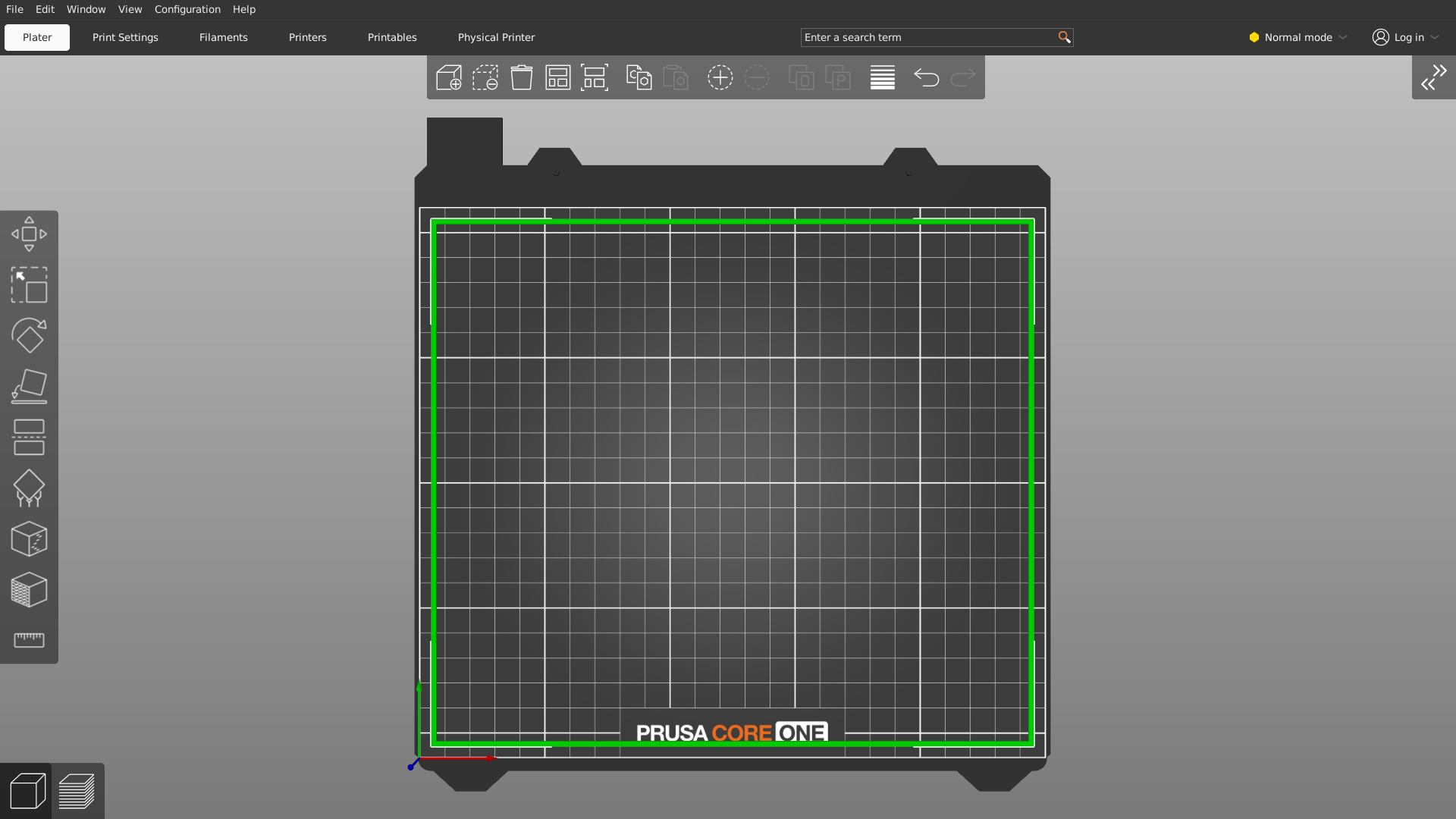
Core XY alignment test object as shown by Prusa Slicer
- Here are resource links for the above-displayed test object, which is an empty square with 1mm border, dimensions 240mm by 210mm, which leaves a 5mm border on the Prusa Core One print bed:
NOTE: The tensioning method described here is more or less what Prusa recommends here, but with important changes and updates.
Overview
The Prusa Core One relies on a long belt and a system of pulleys to move the print head along the X (left/right) and Y (near/far) axes. The two primary belt loops are visible in the image below.
As it turns out, belt tensioning is critical to successful operation of the printer, and unlike Z axis misalignments, the printer cannot automatically perform this procedure. Indeed, of the remedies listed in this article, belt tensioning is the most important.
Here's an outline of the belt tensioning method:
- Turn off the printer.
- Move the print head to the position shown below — all the way to the front and to the right.
- Gently pluck the belts like guitar strings, at the center of their long spans, while measuring their frequency.
- While monitoring the belts' frequencies (see below), with a 2.5mm Allen wrench carefully adjust the belt tensions using the tensioners located here (marked by squares):
Core XY Belt Tensioner Locations (click for full-size)
- Use a frequency meter (see below) to measure the frequency of the plucked belts.
- Interactively pluck the belts and adjust their tensions as explained above, until both belts are tuned as close to 95 Hz as is practical.
- It's important that both belt loops (it's all one long belt) be tuned to the same frequency, in any case within a few Hz of each other, and as near to 95 Hz as practical.
- At the time of writing, the Prusa help page describes two frequencies, one for the lower belt loop, another for the upper loop, but because it's all one long belt, acquiring a specific frequency differential isn't plausible in field practice. If the reader notices a frequency differential between the loops (very likely), it would be better to set an average frequency of 95 Hz using this equation:
$ \displaystyle \frac{(UBF+LBF)}{2} = 95 $
Where:
- UBF = Upper Belt Frequency
- LBF = Lower Belt Frequency
- NOTE: a number of Prusa Core One users report that their belt tensioners failed after multiple uses, making further belt adjustments impossible. I had the same experience, so I designed a printable tensioner upgrade, fully described below — look for "Belt Tensioner Upgrade" later in this article.
At this point my readers will ask, "Wait ... how do I measure 95 Hz?" Here are some available methods:
- The cellphone-compatible Prusa Mobile App, which includes a marginally functional frequency measuring method (Android link | IPhone link). This is the least usable method.
- An Android app called "Spectroid" (download link), much superior to the Prusa method, only available on the Android platform.
- Other frequency measuring utilities are available for the IPhone platform, which unfortunately I cannot test.
But wait ... I provide a:
Test Signal Generator
To evaluate a cellphone frequency-detecting app in advance of trying to tune your printer's Core XY belts, here is a signal generator that provides a reliable 95 Hz signal for testing:
| | Gain: 50
- Press the Start/Stop button at the left and move your cellphone near your computer's speakers to pick up the signal.
- Adjust the speaker gain as required to make the signal audible, but without overloading your computer's audio system.
- Use this test signal to learn how to use your chosen frequency-measuring app in advance of actually trying to tune your printer's belts.
Frequency Measuring App Evaluation
Again, the Prusa Mobile app includes a way to measure the belt frequency, but it's not very good. It may take an unconscionably long time to respond to signals, meanwhile telling you that:
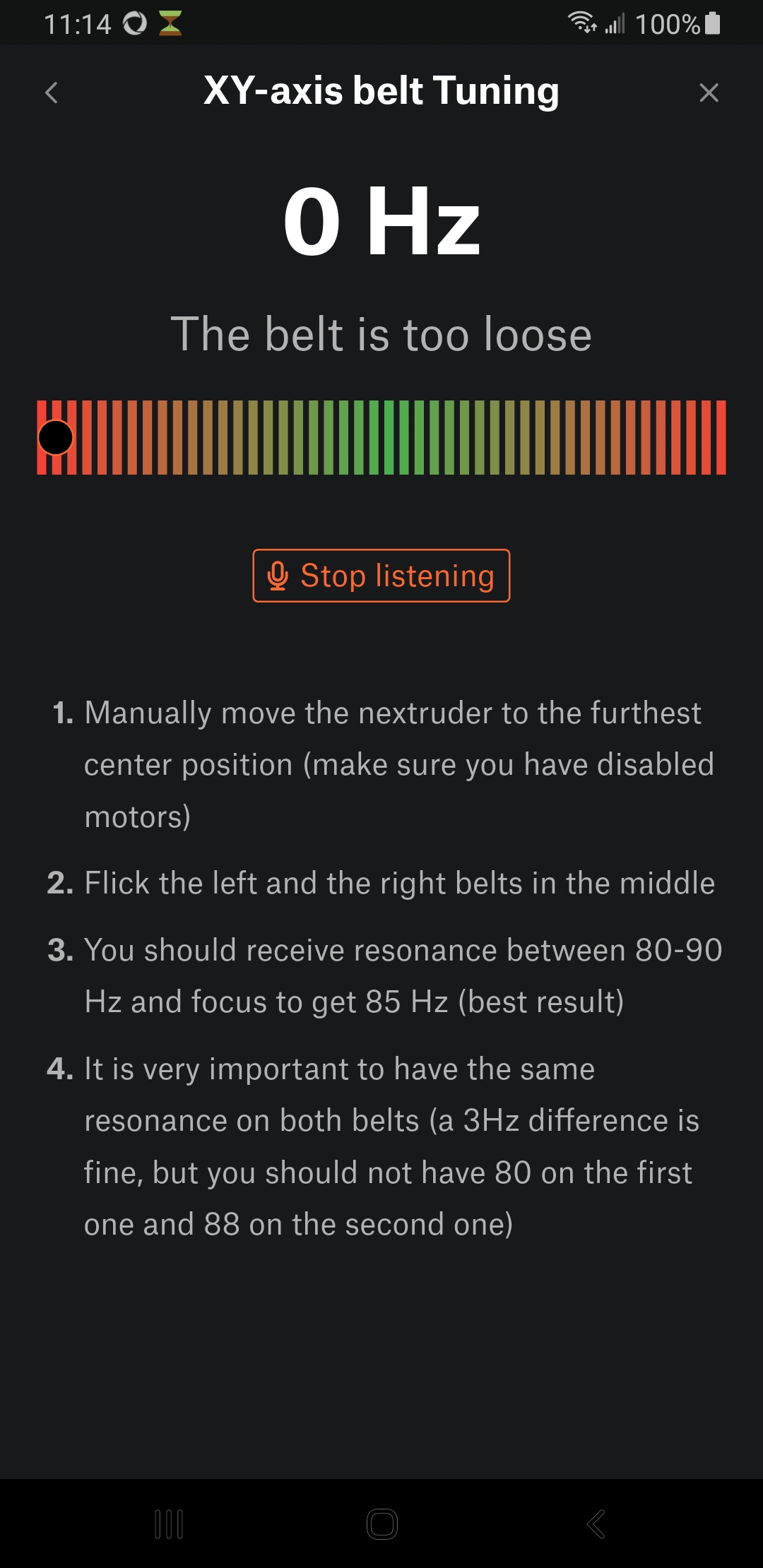
Prusa Mobile App Typical Display
A warning — don't assume that the Prusa Mobile app is providing correct information. If you assume it's accurate and expect it to respond in a timely way, you may overtighten a belt, with numerous consequences, all of them bad. Apropos, in early tests I trusted this frequency gauge, overtightened one of the belt tensioners and stripped it — see below for the full story.
By contrast, here is the Spectroid app display under the same circumstances, which responds instantly:
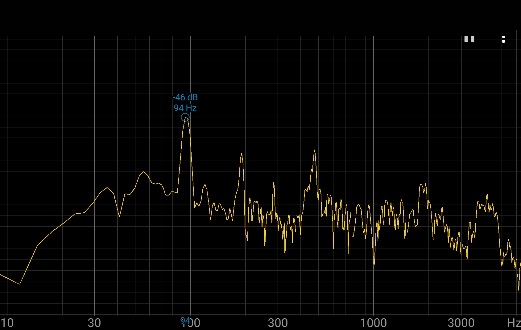
Spectroid (Android) Typical Display
Much better.
In a nice symmetry, many 3D printer problems can be fixed by using the printer to create new parts, certainly true for this printer. Here are some online resources:
- Prusa Core One printable parts — the linked page lists a number of free downloads: a complete set of parts, or parts tuned for different print filaments, or parts by category.
It's desirable to print certain spare parts in advance of possible printer difficulties, after which it may not be possible to use the printer to create new parts. For example, in early experiments I stripped one of my belt tensioners (which turns out the be a common issue — see the section below for a better, user-printable replacement tensioner). Then, in a classic Catch-22, to print a replacement tensioner, I had to temporarily tension the printer's belt with baling wire:


Jury-rigged belt tensioner (click for full size)So the moral of the story is — print spare parts before they're needed. And keep some baling wire handy, just in case.
On that topic, see below for details on a project that replaces the original belt tensioner.
In this article's later sections I present projects that readers can modify to suit their own tastes and needs. For each project, readers can simply print the provided printer-ready STL files without any changes, but I also include Python source files as well as SolveSpace files in some cases, so readers can customize projects for their own needs. In this section I show how to install computer programs and libraries to make these customizations possible. Remember, if you don't want to change the provided STL 3D printing files and simply print them, these installs aren't required.
Here are installation instructions for Windows and Linux:
Windows installation:
- Python and pip:
- Go to this website, download the most recent Python version and install it.
- During the installation, the installer will offer to also install "pip," a package management utility — Be sure to include this package.
- The Python installer will also offer to include Python in the Windows file search pathway — be sure to include this option.
- After the install is complete, open a command window for the next phase — use the Windows search feature to locate and run "cmd.exe" (click the image below to see more detail):

- In the command window, use the "pip" utility to install the cadquery library and cq-editor (click the image below to see more detail):

- Prusa Slicer:Go to this website, download and install the current version of Prusa Slicer.
- SolveSpace: Go to this website, download and install SolveSpace. On my YouTube video channel (https://youtube.com/@lutusp), I include a number of SolveSpace tutorials — here's one.
Linux Installation:
- The Linux install method is much the same as Windows, except of course, easier (Python and pip will already be installed). This installation similarity results from the fact that Windows is slowly and incrementally being taken over by Linux. To install the cadquery library and cq-editor, assuming a recent Debian-derived Linux distribution, open a command shell and enter "pip install cadquery cq-editor --break-system-packages". (click the image below to see more detail):

- To install Prusa Slicer, go to this web page and follow the instructions.
- To install SolveSpace, go to this web page and follow the instructions. On my YouTube video channel (https://youtube.com/@lutusp), I include a number of SolveSpace tutorials — here's one.
Python source (GPL licensed) / SolveSpace Dimensions Worksheet / Belt Tensioner STL
Disclaimer: Because this project involves hardware changes to your printer, and because people's mechanical skills vary widely, I accept no responsibility for bad outcomes or voided warranties — or anything else I haven't thought of.
Since this printer's introduction, a number of reports have appeared in which a belt tensioner stripped out and became unusable during normal calibration actions. A close look at the original tensioner shows why — the factory-supplied plastic tensioner relies on an internal metal square nut to carry the belt tension load and screw turning forces as well (below, left). But because the tensioner is plastic and because belt tuning forces are relatively high, printer owners sometimes report that the square nut has begun to spin freely within the plastic part, making further calibration impossible. I had this experience along with many other printer owners.
This project replaces the factory tensioner — and the square nut — with a redesigned part that uses a threaded brass insert, much less likely to fail under load (below, right).


Belt Tensioner Alternatives (square nut versus brass insert) (click for full-size)Here are some details:
I used the SolveSpace dimensions worksheet listed above to design the part and get detailed dimension information for use by the Python/CadQuery program, which generates the replacement part.
To use the replacement part:
- Download and print the STL file listed above, one or two prints depending on your needs (I recommend replacing both tensioners).
- Be sure to use a strong, high-temperature filament for this part — ABS or a similar type. Don't use PLA — it can't stand the forces involved, and the print chamber can get pretty hot as well.
- Heat-press an M3 x 8mm x 5mm brass threaded insert into each part:

Replacement tensioners with brass inserts installed (click for full-size)
- Replace the original tensioners with this part. This part uses the original tensioner's associated hardware without changes.
- Retune the printer's belts as explained earlier in this article.
This replacement has many advantages over the original. Apart from being much less susceptible to stripping out, it tracks the user's fine adjustments more accurately — compared to the orignal, whose square nut, when it wasn't stripping out, would turn a bit on each direction reversal before responding to the user's intentions.
Some filaments emit toxic fumes during printing, and if a 3D printing location is shared by people and pets, an air filter is a good idea. This project 3D prints a two-element air filter housing that uses economical, readily available activated carbon HEPA filter cartridges. Because typical filter cartridges aren't small, printing Element B of this project requires nearly the entire Prusa Core One print space:

Air Filter Element B shown in Prusa Slicer (click for full-size)Here's a video of the installation process:
This project has these parts:Air Filter Assembly Sequence Video
- Element A (SolveSpace / STL) connects flush to the Prusa Core One rear panel with four M3 x 20mm screws and washers, using provided mounting points.
- Element B (SolveSpace / STL) mounts on top of Element A, offset from the printer's rear panel, and accepts an air filter.
- Air filter, P1801/P1802, size 235mm L, 202mm W, 22.1mm H (9.25" L x 7.95" W x 0.87" H), listed at this Amazon page in Summer 2025. Since this link will expire in time, just look for filters by their generic part number: P1801/P1802 and pay heed to dimensions.
- If the reader prefers a different filter, the above-listed SolveSpace project file for Element B can be edited to accommodate different filter sizes.
- 4 M3x20mm screws and M3 washers for mounting to the printer (the printer has correctly positioned pre-threaded holes).
The reason this project has two elements is to avoid mounting a large fan enclosure flush against the printer's rear panel, while avoiding overhang issues during printing. Element A provides an offset from the rear panel, while Element B accepts the filter. Both elements print without overhang issues.
The air filter listed above isn't anything special and can be replaced, and if so, the Element B SolveSpace file can be edited to accommodate different dimensions. Among the advantages of large filters are that they don't stress the printer's fans very much and they will have a long service life.
Prusa offers a camera named "Buddy3D" for the Core One, but it has a number of drawbacks:
- Unless there is more light available than is typical for the Core One print volume, the camera provides monochrome images.
- The camera updates its image only once every ten seconds.
- Without an Internet connection, the camera stops working.
- Use of the camera requires a Prusa Connect account.
I think Prusa is a terrific company that has made many contributions to 3D printing over the years, but when I hear they require a Prusa account to use their camera, I want to consider a different one — and this section provides it.
The Basics
This project uses a 3D printed camera mount, some magnets, and an inexpensive color camera.
WARNING: This project relies on small magnets, magnets that pose a serious danger if ingested, as explained here. If you have young children in your household, keep firm control over the magnets when they're not attached to the camera mount. Don't let young children play with them.
Let me explain a bit. The magnets aren't themselves toxic, indeed they're quite safe. The problem is that if a child swallows more than one, the magnets powerfully attract one another in a person's intestines, causing a potentially fatal blockage. So ... keep them away from small children.
The 3D printed mount looks like this:
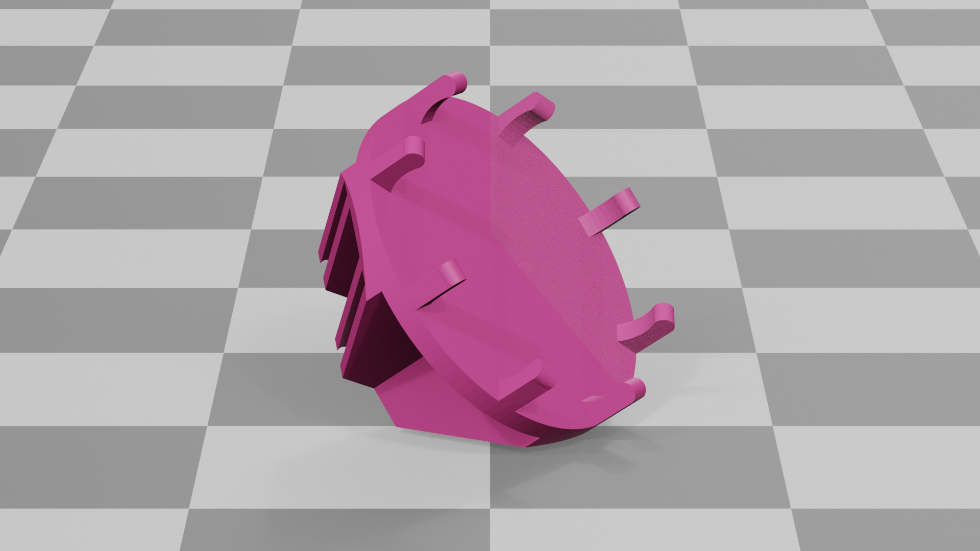
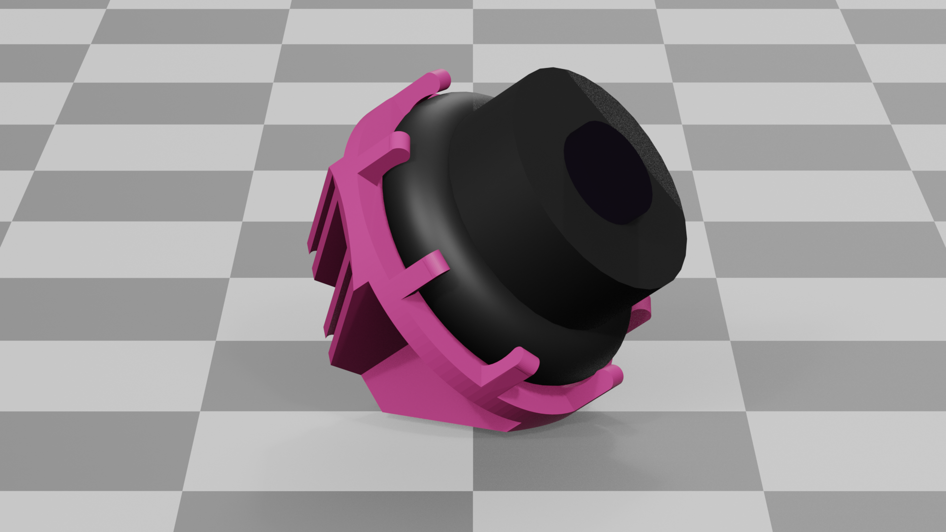
3D printable camera mount as rendered by Blender: without camera | with cameraHere's a list of resources / links for the camera mount:
- A SolveSpace design file for the mount, for those who need to customize the design, perhaps for a different camera.
- A printable STL file for the mount, suitable for the Yi camera listed below.
- A Prusa Slicer file containing the mount, with appropriate settings for ABS printing on the Prusa Core One.
- NOTE: If you create your own Prusa Slicer profile for this project, be sure to enable supports, like this:


Prusa Slicer print configration with organic supports (click for full-size)- Neodymium magnets, length 27mm, diameter 6mm, Amazon link, need 6.
- A small inexpensive camera, manufacturer Yi, Amazon link.
- A micro-USB to USB-C adaptor cable to power the camera from the printer, Amazon link.
NOTE: All these links will become invalid over time. I hope I have provided enough detail so the items can be located anyway.
Using Spring 2025 prices, this camera setup costs about US$42.00 altogether, only because one cannot buy just six magnets. This is slightly more expensive than Prusa's Buddy3D camera.
The Yi camera has a micro-USB connector, but the Prusa Core One has a USB-C power connector, so an adaptor cable is included in the above list, to use printer power for the camera.
Use of ABS filament is probably not required. I normally use ABS for durable parts that need to tolerate elevated temperatures, but I haven't tested other filament types, some of which may work correctly in this project.
Setup Instructions
When the above parts list is complete and the mount has been printed, take these steps:
- Slide six neodymium magnets into the slots provided in the 3D printed mount. Make sure all the magnets are inserted with the same polarity, i.e. the magnets should have either their North or South poles all pointing toward the center of the mount.
NOTE: to compare the polarity of two magnets, place one magnet alongside another.
- If the magnets resist being brought together, their polarities are the same.
- If they snap together, their polarities are opposite.
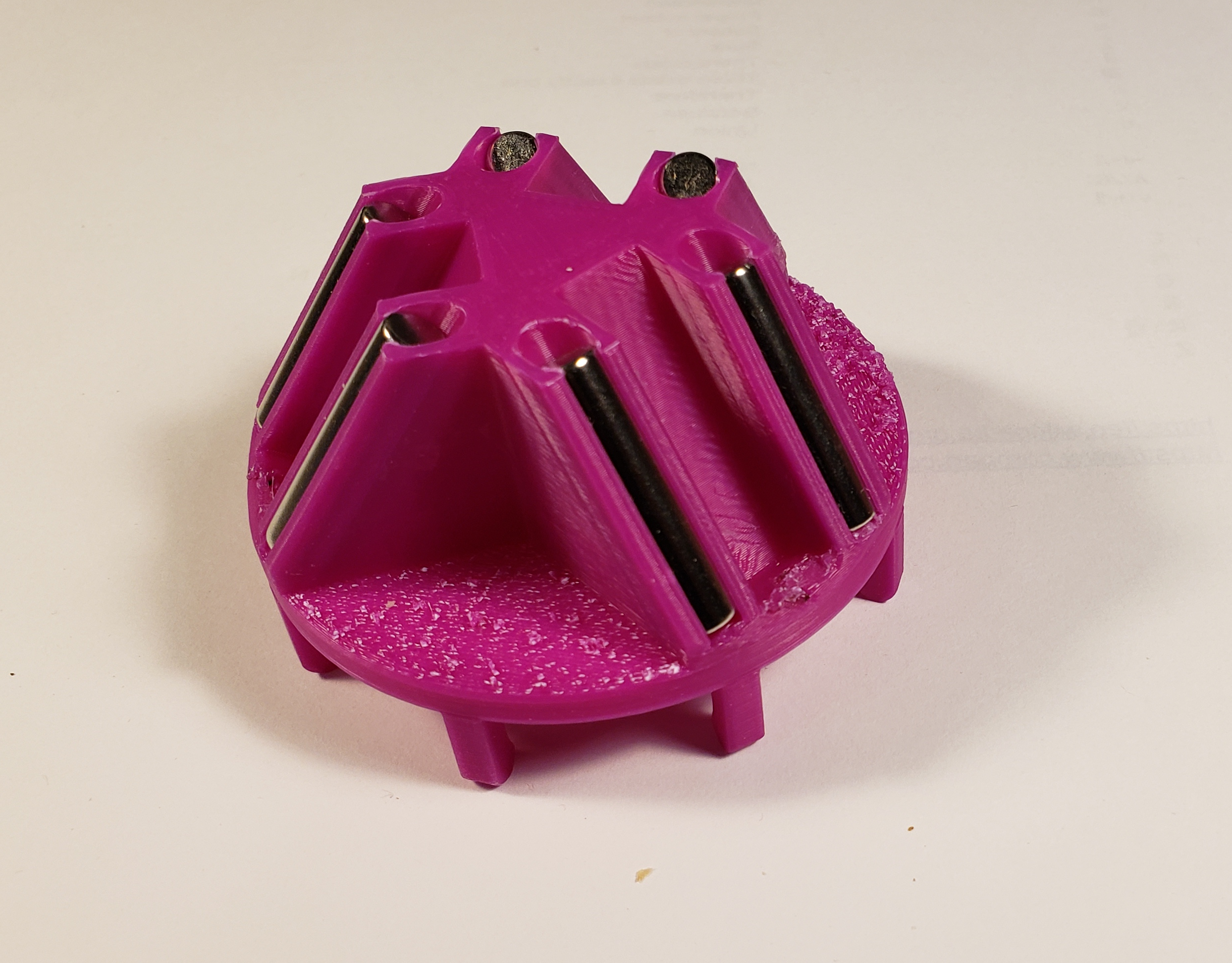
Mount with installed magnets- Remove the Yi camera from its tabletop support.
- Snap the Yi camera into the gripping fingers on the front face of the mount.
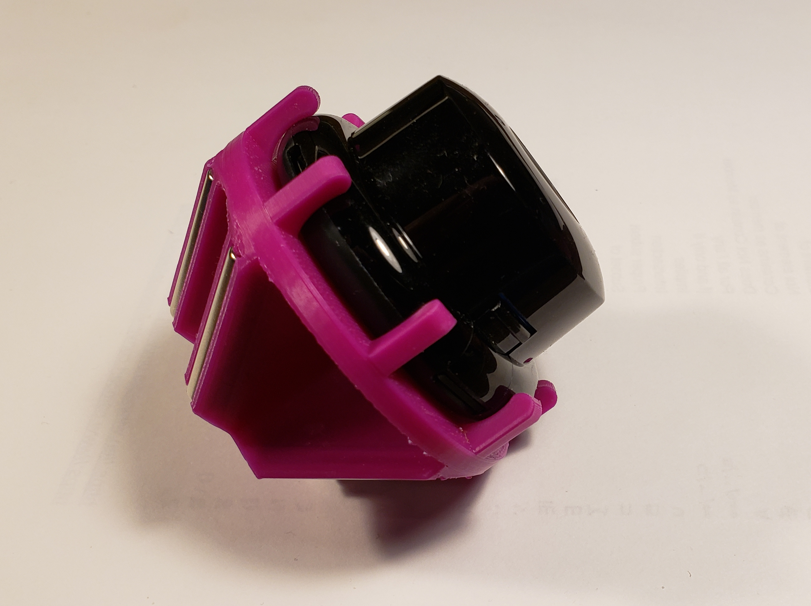
Mount with magnets and Yi camera- Here is the camera mount, correctly positioned at the front upper left interior of the Prusa Core One enclosure:
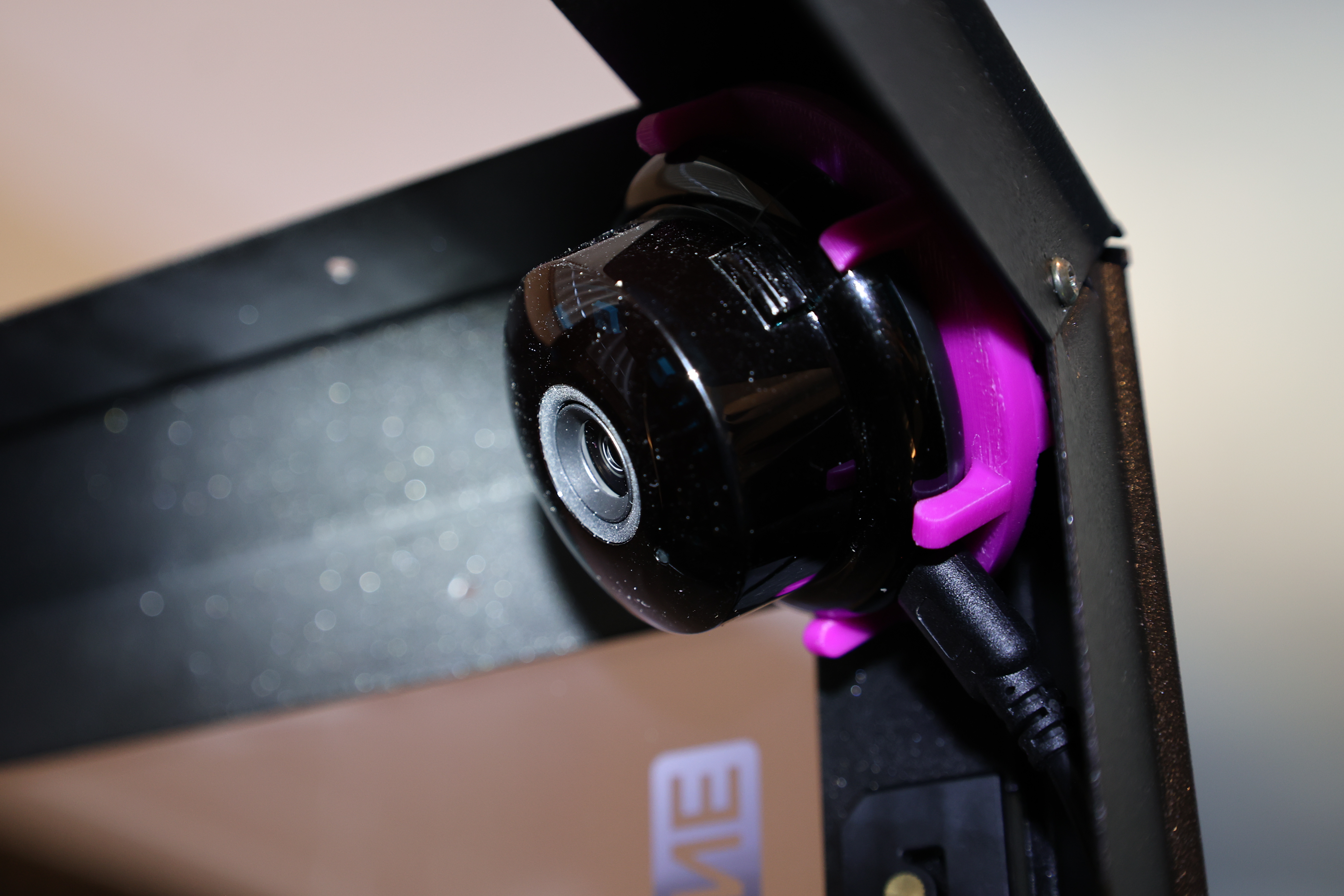
Camera Mount in Service- Using these instructions, route the USB adaptor cable from the Prusa Core One's USB-C power outlet to the upper left inside location where the Buddy3D camera would normally go.
- Connect the USB-C end of the adaptor cable to the Prusa Core One USB-C power connector.
- Connect the Micro-USB end of the adaptor cable to the Yi camera.
- Check for clearance and cable routing, then position the camera mount near the printer's upper left inside corner and release it.
- Make sure the mount is located symmetrically in its corner and firmly gripped by the magnets. Rotate the mount to be sure.
- With printer power off, move the print head to position Y = 0, X = 0 (the position nearest the camera) to make sure there is no collision possibility between the camera and the print head.
- Power up the printer and test the camera's wireless network connection. Make sure you have a clear picture of the print bed.
- To maximize the camera's usefulness, set the chamber light brightness to 50% or higher and disable dimming. Use this command sequence from the printer's main menu:
- Settings
- User Interface
- Chamber Lights 50-100%
- Chamber Dimming Off
Home Assistant Compatibility
The little camera described above is compatible with Home Assistant, a free, powerful home automation scheme. Among many other things, this software allows these little cameras to display a normal TV frame rate, which otherwise might provide a sequence of still pictures, not very useful.
Third Party Camera Firmware
Without any changes and like every modern TV camera, the above-described Yi camera is over-reliant on company resources and connections. But a first-rate, open-source, third-party project solves this issue for this very popular camera, so it no longer phones home — here's a link. If you acquire the same camera model as that listed in the Amazon ad, its firmware prefix should be y211ga, usable as a search string at the linked firmware site.
Or perhaps you have located some other small, inexpensive security camera that, with no changes, doesn't try to phone home. If you have, please tell me about it at my message page. This isn't likely, but anything is possible.
Here are some recommendations for 3D design software and the best slicer to use with the Prusa Core One.
CAD/CAM Design
Some of my readers know I've created a few videos about SolveSpace (example), a free, open-source, multi-platform computer design program. I recommend it for students and for those who prefer open-source programs over the alternatives. Here's the camera mount described above, as shown by SolveSpace, where it was designed:

Camera Mount design in SolveSpace (click for full-size)Many alternatives to SolveSpace exist, but most are either too buggy and hard to use (FreeCAD), or they own both you and your projects (Fusion 360). SolveSpace has a rather steep learning curve and is missing some features many people regard as important (like the ability to create numeric dimensioning variables), but it's both free and pretty good. It's more than adequate for projects like those in this article.
Best Slicer Program
In my opinion, the best slicer program for the Prusa Core One is created by Prusa, named PrusaSlicer. The big advantage of PrusaSlicer is that it knows about the Prusa Core One and includes profiles for many filament types, with parameters tuned specifically for the Prusa Core One. This is a huge advantage over the common, time-consuming practice of tuning a slicer program to accommodate an unknown printer and a 3D printing filament of uncertain properties.
Another PrusaSlicer advantage has to do with print speed. Without inside knowledge of a printer's mechanical properties, a slicer program isn't likely to know how to balance print speed and quality. But PrusaSlicer understands the Prusa Core One intimately and has been extensively tested in order to maximize performance and print quality.
This section describes some of my magnet-related projects — projects where 3D printed parts are dynamically assembled by modern, inexpensive, high-powered magnets.
WARNING: If you have young children in your household, I recommend that you pass up these magnet projects, because young children may swallow small magnets, which can have serious, even fatal, health consequences as described here. A quote from the linked article: "Tiny magnets, like the ones found in building sets and other toys, can cause death in kids if more than one is swallowed. The U.S. Consumer Product Safety Commission (CPSC) has verified the death of a 20-month-old and at least 19 other small children being injured and requiring surgery."
Let me explain a bit. The magnets aren't themselves toxic, indeed they're quite safe. The problem is that if a child swallows more than one, the magnets powerfully attract one another in a person's intestines, causing a potentially fatal blockage. So ... keep them away from small children.
These projects rely on inexpensive neodymium magnets, 27mm long, 6mm in diameter. Here's an Amazon link (2025.07.18), but don't be surprised if this link become invalid in time and you have to search for them.
The basic idea behind these projects is that you 3D print individual parts of a geometric object, add some inexpensive neodymium magnets to the edges of the parts, then the finished object is held together by the force of magnets. And in some cases the printed parts literally fly together under the force of magnetism. Here's a step-by-step example:
Design one surface of a multi-sided geometric object, making sure to include mounting points for magnets. Here's a SolveSpace design image for one surface of a small cube (source listed below):

Cube Face Design in SolveSpace (click for full-size)3D print as many copies of the basic design as the object requires:

Cube Face Design as shown in Blender (click for full-size)Add magnets to each part, remembering to keep the magnetic poles consistent — either North-pole counterclockwise, or the reverse, but consistently across all the parts:

Cube Face Design with Magnets, as shown in Blender (click for full-size)Here are real-world images of the small cube project, from individual parts with magnets in place, to fully assembled:


Cube Assembly Sequence, as shown in Reality (click for full-size)Again, remember about these projects that the magnets must be all polarity-aligned, either North or South poles arranged in a circle, or the reverse, but all magnets and all parts the same:
Magnet Polarity Test (click for full-size)HINT: Use this trick to compare magnets: if you try to press one bar magnet against another and you feel resistance, this tells you the magnets have the same polarity. If the magnets snap together, they have opposite polarities.
Here are some of my magnet-based projects, with SolveSpace design and printable STL files:
- Tetrahedron (4-sided object): SolveSpace / STL. Four sides, each with 3 magnets: 12 magnets.
- Small cube (shown above): SolveSpace / STL. Six sides, each with 4 magnets: 24 magnets.
- Large cube: SolveSpace / STL. Six sides, each with 8 magnets: 48 magnets.
- Dodecahedron (12-sided object): SolveSpace / STL. Twelve sides, each with five magnets: 60 magnets.
- Icosahedron (20-sided object): SolveSpace / STL. Twenty sides, each with 3 magnets: 60 magnets. This variation is a work in progress.
This section provides multi-sided objects that assemble with symmetrical mechanical fasteners instead of magnets. These weigh and cost less than magnet projects, and they're safe for young children. The symmetrical fastener I designed, used in all versions of the project, looks and works like this:
Mechanical fastener cube video
The basic idea of this symmetrical fastener scheme is that one need design only one face of a multi-face object, print as many copies as there are faces in the object, then assemble the faces. In the above cube video, I only needed to design a single face, after which I printed six copies. For the dodecahedron listed below, I designed one face, then printed 12 copies.
For various reasons and unlike other projects shown here, designing these projects relies on (a) the Python cadquery library, and (b) CQ-editor, an interactive cadquery graphics development editor. Developing these mechanical fasteners requires a lot of interaction and tuning, so an editor with graphic feedback is esssential.
The projects listed below are scalable without losing proportions, using a single variable. Normally one sets Python script parameters, then generates some test STL results, then examines the STL results in a graphic environment like Blender, then finally, 3D prints some actual parts.
Cube: Python source (GPL licensed) / STL. This project is shown in the above video. To build the cube, one must 3D print six copies of a single polygon design, then assemble them using their mechanical fasteners.
Dodecahedron: Python source (GPL licensed) / STL. This project creates a model of a classic Roman-era dodecahedron whose original purpose no one has figured out. Here's a reference. Only about 130 are known to exist, all built between the second and fourth centuries CE.
To build this project, one must 3D print 12 polygons, then assemble them into their final form. This model optionally supports (and generates) vertex pegs, one of the distinctive features of the original Roman dodecahedrons.
During development work on this project, I tried 3D printing the entire dodecahedron in one go, but because of the object's shape, it wasn't possible to print it without distortions and failures caused by overhangs. So I started over, printing 12 polygons and 20 decorative pegs separately, then assembling them. Because each polygon face lay flat on the print surface instead of being suspended in midair, printing issues were resolved.
Here's what this project would look like, in a perfect world, with perfect 3D printers:
Mechanical fastener Roman dodecahedron video
This video was rendered by Blender, after a lot of fine tuning. An actual 3D print won't look remotely like this, it's only meant to show the basic idea.
Icosahedron: Python source (GPL licensed) / STL. This is a 20-sided polyhedron using my mechanical fasteners to unite 20 triangular sections. To create it, one simply prints 20 copies of a single prototype object, then assembles them:


Icosahedron before (left) and after (right) (click for full-size)
In this section I list some of my (non-magnet) 3D printing projects, each with SolveSpace design files, printable STL files, and instructions.
General Project Source Files (SolveSpace and STL)
- 3D calibration test cube (SolveSpace / STL) — a classic 3D printer calibration aid, 20mm per side, with printed labels showing the cardinal dimensions X, Y and Z. For the labels, users will need to specify a locally available TrueType font, which for licensing reasons is not included in the source file.
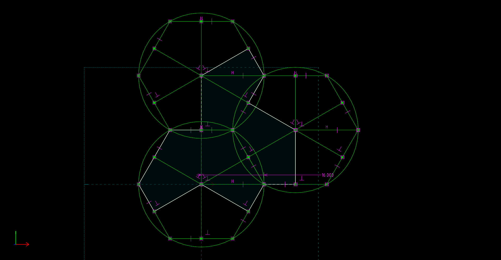
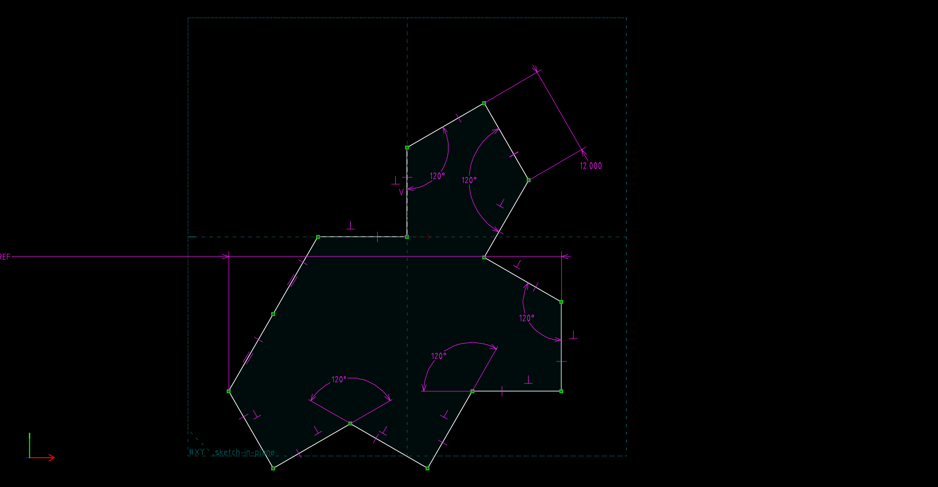
- Aperiodic Tile version 1 (SolveSpace / STL) — This is a printable aperiodic tile as explained in this Scientific American article. Unlike Spectre below, this aperiodic tile version requires that the tile's mirror image be used at times. In this SolveSpace design, three hexagons are constructed, then the perimeter of the tile is created using coordinates provided by the hexagons. Click here for an image of the key sketch. Notice that the majority of the lines are construction lines, meaning lines that provide dimensioning/geometry but don't become part of the exported sketch.
- Aperiodic Tile version 2, i.e. Spectre (SolveSpace / STL) — this aperiodic tile model does away with the requirement for a mirror image of the pattern. Many have argued that this is the only true aperiodic tile design. See An aperiodic monotile for a full explanation. Click here for an image of the key sketch.
- Bike mirror mount (SolveSpace / STL). This is the flexible mirror mount fully described at this link.
- Cup, 400ml (SolveSpace / STL). This is a relatively simple, useful cup design that shows a few intermediate to advanced methods to accomplish its design. Like the calibration cube listed above, because of a capacity label printed at the bottom of the cup, this project also requires specifying a locally available TrueType font.
- Cup, Advanced Design, 400ml (SolveSpace / STL). This is a more practical cup that goes beyond a simple tutorial design.
- Metric M10 size threaded bolt (SolveSpace / STL). This design creates a working, practical Metric bolt of M10 size. This SolveSpace design file can be rescaled for other Imperial and Metric hardware sizes. It uses the SolveSpace helix feature and some careful dimensioning to make a practical bolt correctly sized to mate with a 3D printed nut (see below) or a metal nut of the same size.
- Metric M10 size nut (SolveSpace / STL). This project correctly interacts with the bolt listed above, or with metal hardware of the same size. As with the bolt listed above, this nut can be rescaled as required for other Imperial and Metric sizes.
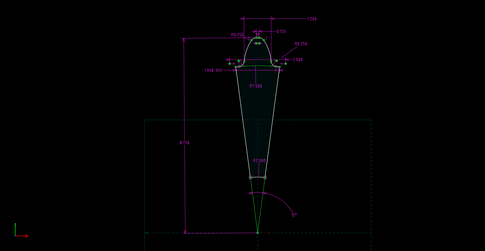
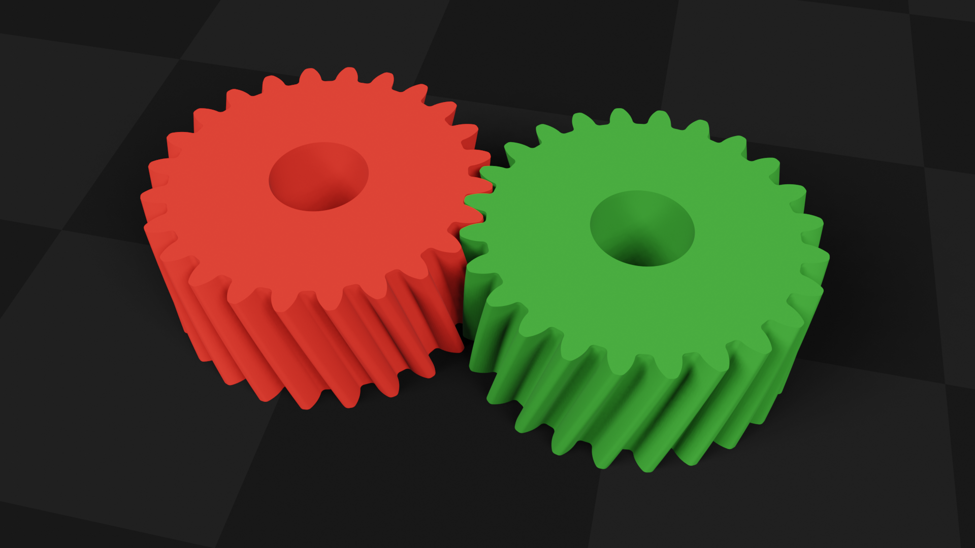
- Helical Gear (SolveSpace / STL). An exercise in advanced gear design. Click here to see the primary sketch. Click here to see a Blender view of the meshed gears.
- SolveSpace Container Tutorial Files:
These are files to support my YouTube SolveSpace container tutorial.
- Container: SolveSpace file / STL file
- Cover: SolveSpace file / STL file
Special Projects and ResourcesIn this section I list projects based on Python and the CadQuery library. These projects require that Python and CadQuery be installed on your machine.
BoxBuilder: Python source (GPL licensed) / example_box.stl / example_cover.stl

BoxBuilder Example Result (click for full-size)The Boxbuilder Python source includes clearly named dimension variables for project wall thickness, box width, height, depth and corner radius. Because this program creates a cover as well as a box, the cover's dimensions are defined by the box dimensions except for a cover edge height variable and a clearance variable that adjusts the tightness of fit between the box and the cover. To use this program:
- Edit the source — change the file output name if desired, and set dimension variables to meet your requirements.
- Run the program — the printable STL files will be saved in the box builder's program directory.
- Print the resulting STL files.
In my build tests for this project, I printed using ABS filament on the Prusa Core One, but other printers and filament materials may require a change in the program's fit tightness variable. Remember that the fit tightness variable only changes the cover's dimensions, not that of the box, so if a change is needed, only the cover would need to be reprinted.
Filament Reel Holder: Python source (GPL licensed) / reel holder STL file / cover STL file

Filament Reel Holder Body and Cover (click for full-size)This project builds a filament reel enclosure to prevent moisture absorption while printing is under way. Many filament types (TPU and nylon to name two) are very hygroscopic (prone to absorb moisture), and even after advance dessication, such filaments will absorb moisture from the environment while printing is underway. This project helps guard against that possibility.
Inside the enclosure, the filament reel spins freely on an internal axle, and a small opening at the top guides the filament to the printer.
To change this project's dimensions, edit the source and change the clearly named variables. I include these control variables because not all filament reels have the same dimensions (the defaults are set for Hatchbox filament reels). But larger filament reels may exceed the printing size of the Prusa Core One. Even with the Hatchbox reel defaults, printing this project requires nearly every square millimeter of the printer's X and Y dimensions.

Filament Reel Container size in Prusa Slicer (click for full-size)To use the reel holder:
- Place the reel holder at the right side of the Prusa Core One, adjacent to the machine's default reel axle.
- Remove the desired filament from its moisture-free storage location and place it adjacent to the reel holder.
- Pass the filament's free end through the port located at the top of the reel holder's main body and into the Prusa Core One's filament tube.
- Now place the filament reel onto the reel holder's internal axle
- To protect your filament from moisture during printing, close the reel holder with the provided cover.
- Position the reel holder to minimize friction along the filament path.
It would be nice to print this project using a transparent filament, which I'm told now exists, so the reel's motion could be observed without opening the enclosure.
| Home | | 3D Printing | | | Share This Page |
