

 Share This Page
| Home | | Ham Radio | | | | Share This Page |
An easy way to improve my signal generator's accuracy
— All content Copyright © 2018, P. Lutus — Message Page —
Most recent update:
(double-click any word to see its definition)

Figure 1: Homely circuit board in metal enclosure
I have a Siglent SDG 1025, an inexpensive signal generator that's satisfactory in every way except one — its frequency accuracy isn't very good and there's no way to adjust it.
As it happens, this Siglent model will accept an external 10 MHz clock standard to improve its accuracy, so I looked into buying or creating one.
I required this signal generator to provide accurate test signals as part of my recent PLSDR software-defined radio project. The Siglent provided many kinds of signals I used to validate and improve PLSDR.
I ended up using mostly junk-box parts to build a cheap and dirty frequency standard that reduces the generator's clock error to less than .1 PPM (i.e. 1 Hz at 10 MHz) and that's likely to stay on frequency over months or years. This sort of project is much easier and less expensive than it would have been during my prime years in electrical engineeering (decades ago, before I got into computer science).
Because I wanted the outcome, not the experience, the end result is a bit of an ugly ducking and I'm glad it spends most of its time sealed up in its little metal box. After about five minutes of warmup time it's very stable, reliable and cost under US$40.00 (not counting the junk-box parts that tie it all together).
This project went through several revisions and failed digressions before I settled on its final form. I originally intended to acquire a TCXO (Temperature Controlled Crystal Oscillator), which has the advantage of using very little power and not requiring any warm-up time, but is less accurate than an OCXO (Oven-controlled Crystal Oscillator), which forces its quartz crystal oscillator to a fixed temperature within a few minutes of activation, after which it's very stable. This device requires some current to force the crystal to a specific temperature, but surprisingly little — 500 milliamperes initially, and about 200 milliamperes steady-state after warm-up. A normal USB connection should easily provide this amount of current.
At the beginning of the project I naively ordered an inexpensive TCXO, only to discover that it was so small that it couldn't be handled by mere mortals equipped with crude macroscopic (i.e. insufficiently tiny) soldering equipment ... and fingers. Lesson learned, I then ordered a device with a much larger package size, so it could tolerate the indignity of being soldered onto a circuit board using the crude methods I learned decades ago and that have nearly disappeared in modern times.
After a preliminary evaluation, I realized the circuit was radiating too much energy into its environment at 10 MHz, so I:
- Moved the project from a plastic to a metal box.
- Added L1 and C1 to prevent RF leakage through the power leads.
- Rewired the board and connectors to avoid ground loops.
A careful look at Figure 1 (click the image for full scale) will show that all the project's ground leads now converge at a single point — the BNC connector at the right. This is a classic remedy for ground loops, and the result of the above remedial steps is a nearly complete absence of 10 MHz leakage in a room where sensitive shortwave receivers are operating. I eventually arrived at the schematic shown in Figure 2.
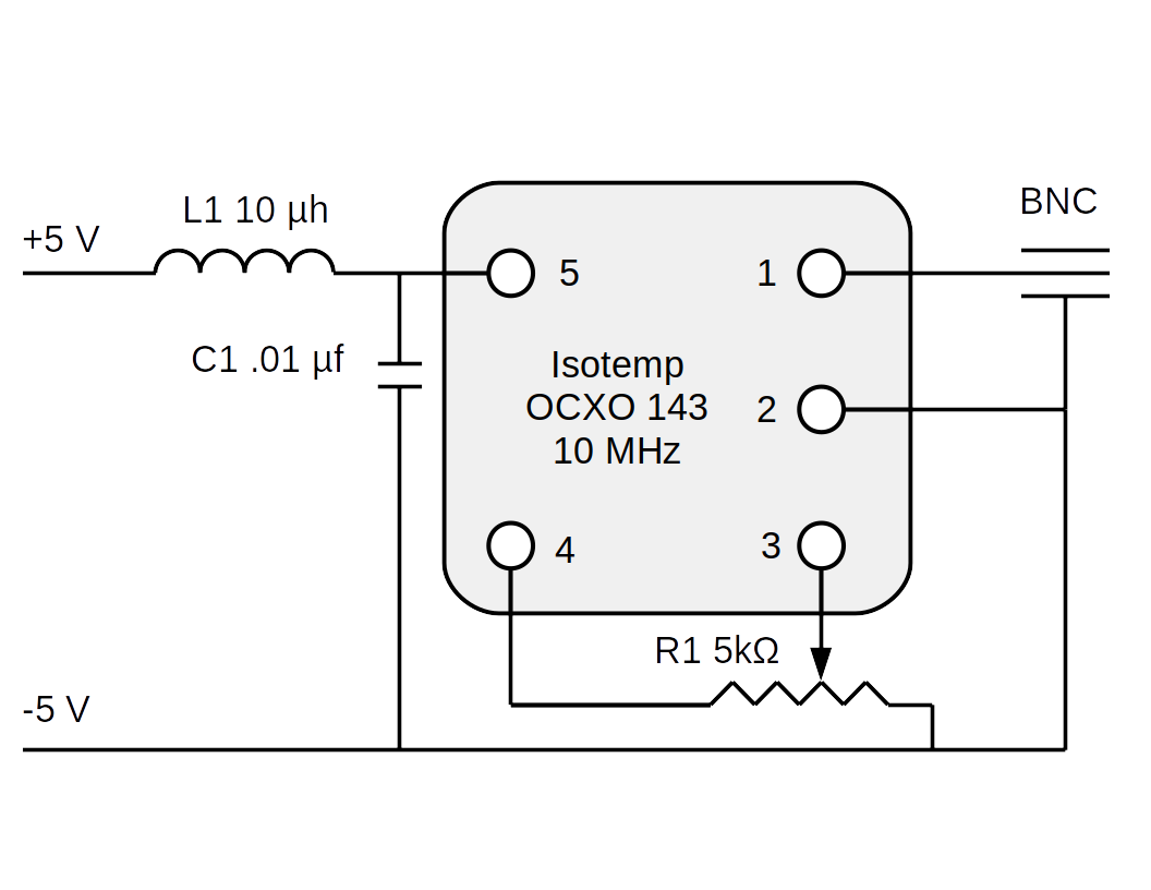
Figure 2: Project schematic diagram
Isotemp 143-series pinout:
- RF output
- Common
- VCO calibration input
- Reference voltage
- +5 Volts
NOTE: Not all Isotemp units have the same pinout — see this specification sheet for the variations.
Calibration
After eliminating 10 MHz radiation as an issue, I moved on to calibration (the purpose of potentiometer R1 in Figure 2). The best comparison reference for everyday use is WWV, the U.S. time and frequency standard that operates out of Fort Collins, Colorado and Hawaii and that broadcasts at 2.5, 5, 10, 15 and 20 MHz. Adjusting the frequency standard against an on-air radio signal is a bit tricky, but after adjusting for equal signal levels (using the Siglent's level controls), a zero-beat is easy to hear without special equipment. It's even easier if you use an SDR like PLSDR with a spectrum display — for equal signal strengths, when approaching a frequency differential of zero Hz one cannot hear the beat any more, but the spectral peak rises and falls in an unmistakable pattern that allows adjustment to substantially less than one Hz.

Figure 3: Frequency Standard in use
Figure 3 shows the frequency standard connected to the Siglent SDG-1025. The frequency standard uses the Siglent front-panel USB connector for power, and its output (Figure 3, right) is connected to the 10 MHz external clock BNC connector at the back of the generator. I drilled a hole in the top of the project box so I could adjust calibration potentiometer R1 without having to disassemble the device.
Output Characteristics

Figure 4: System output waveform
Figure 4 shows the system's output waveform when terminated in a 50Ω load. The open-circuit amplitude is about 8V peak-to-peak.
Parts
This is a rather free-form project as far as specific parts are concerned, but certain aspects turned out to be critical, like use of a metal enclosure, an added LC filter and careful component layout to prevent RF leakage. Here are the two key parts:
- Metal box, US$14.00 (any metal box will do, this is just an example).
- TCXO 10 MHz clock (Isotemp 143 series), US$17.00 on Ebay. Again, most similar products will work, this one is relatively inexpensive.
Because it has a BNC output connector, this project should work with most systems that accept a 10 MHz external clock (like the HackRf One device), so my Siglent generator is just one of many applications for such a frequency standard.
| Home | | Ham Radio | | | | Share This Page |
